26
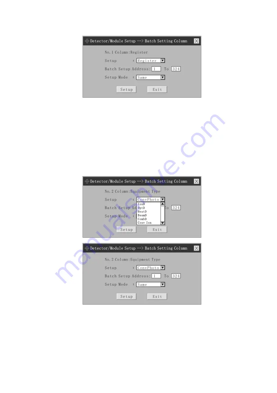
window interface of batch setting column, as shown below:
Figure 4-25 Batch setting column of detector/module
The setting interface is divided into three parts. The first part is to set equipment properties
in the column (if the column header is equipment type, choose to set equipment type. If the
column header is building number, choose to set building number). The second part is start
address and end address of batch setting, with a range of address value of 1-324. The address
number of batch setting column shall also be consecutive. The third part concerns the setting
mode, namely "same", "ascending order" and "descending order". The equipment address
number at the start address is considered as the starting point and the property value of each
equipment is set according to different setting mode sequence setting properties in the first part,
until reaching the end address.
Example 1: double click column header of equipment type and set "interface
photo-electricity" for the first part, with start address 1, end address 324 and "same" setting
mode, then the setting result is as follows: the equipment type of equipment at address 1 to
address 324 is "interface photo-electricity".
Figure 4-26 Batch setting column of detector/module - selection of equipment type
Figure 4-27 Batch setting column of detector/module - setting interface
Other columns can be set in the same way.
4.2.2 Work mode setup
The function of work mode setup allows the user to change work mode of any equipment
on the bus and can change work mode of all the 324 equipment on a circuit one-time.
The work mode setup interface is as follows:


