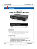
vSync412i User Guide
© vSync DVR December 2007
Rev A.
December 2007
Specifications and content are subject to change without notice.
11
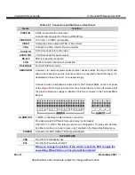
Table 2.2.1. Connectors and Switches on Rear Panel
Name
Function
VIDEO IN
4 BNC connectors for video input
Connect camera output to Video-in (NTSC/PAL)
VIDEO OUT
1Ch VGA, 1 Ch BNC (Composite)
VIDEO
Composite video output in NTSC or PAL format
VGA
Connect to a VGA monitor 15-pin connector
AUDIO IN
4 RCA connectors for audio input
AUDIO OUT
1 RCA connector for audio output
RS-232
POS text inserter connection
LAN
RJ-45 connector for Ethernet connection
RS-485/422
For Pan/Tilt/Zoom control
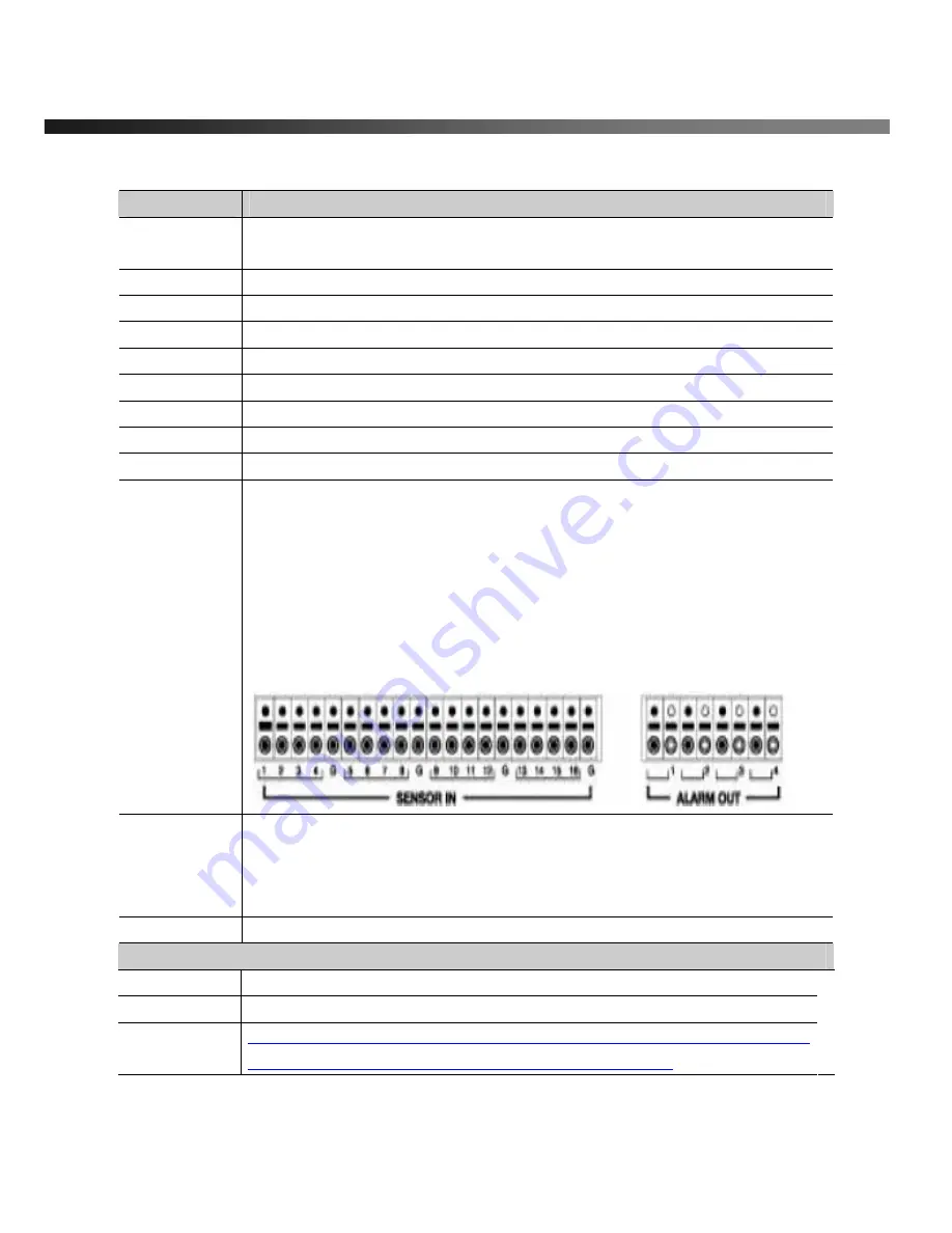
SENSOR IN
Connector for external alarm sensor/contact devices alerts the vSync DVR and
allows it to respond to events. 4 sensors can be connected to the DVR sensor 1~4
dedicated to Video Channel 1~4 correspondingly.
Connect 2 wires to activate a sensor input to the Terminal Block on the rear panel
of the
vSync
DVR. A ground wire from the external device to the unit ensures that
the ground reference voltage is identical. This line connects to the Terminal Block
G
input.
ALARM OUT
1 (PGM) connectors for alarm device connection.
Provides simple On/Off switching using relay (not included).
0.5A/125V or 1A/30V. The relay is open when not triggered. The relay can be close
by either a motion or a sensor input, only if enabled in the Recording Setup menu.
POWER
Connector for AC115/220V 12V/5A power adapter.
DIP SWITCHES
VGA
Turn ON for VGA display use.
PAL
Turn ON for PAL, Default is OFF
When you change the position of the switch, reboot the DVR to apply the
new setting. When VGA is on, Video-Out will be disabled!

