8
SETTING UP YOUR VT 2931
5.
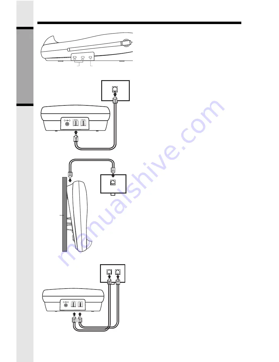
Set the TONE/PULSE switch, located on
the antenna side of the Base Unit, to the
desired dialing mode. In most areas, TONE
is the desired mo
de.
6.
After charging the battery pack, connect
the telephone line(s).
I. If you have 2 lines coming out of
a single wall jack:
Connect a 4-wire (RJ-14) phone cord be-
tween the wall jack and the phone jack la-
beled L1 / L1+L2
.
If you are wall mounting your Base Unit, a
short, 4-wire phone cord is provided for
your convenience.
II. If you have 2 lines, each coming
out of a separate wall jack:
Connect a phone cord from the wall jack
you wish to designate as your LINE1, to
the L1 / L1+L2 jack on the back of the
phone; next, connect a phone cord from
the remaining wall jack to the L2 jack on
the phone.
NOTE: You can use your
VT 2931 as a one-
line phone, as well. For best results, raise
the antenna on the Handset and Base Unit
when using your telephone.
TELEPHONE
WALL JACK
LINE 2
DC
LINE 2
+
-
DC IN 9V
L1/L1+L2
L2
RJ-11
RJ-11
TONE/PULSE SWITCH
BASE RINGER
SWITCHES
L 2
DIAL MODE
PULSE
TONE
L2
OFF
LOW
HIGH
L1
OFF
LOW
HIGH
RINGER LEVEL
TELEPHONE
WALL JACK
LINE 2
DC
LINE 2
+
-
DC IN 9V
L1/L1+L2
L2
RJ-14
TELEPHONE
WALL JACK
WALL
RJ-14
GETTING STARTED


