SCA3000 DEMO KIT
User Manual
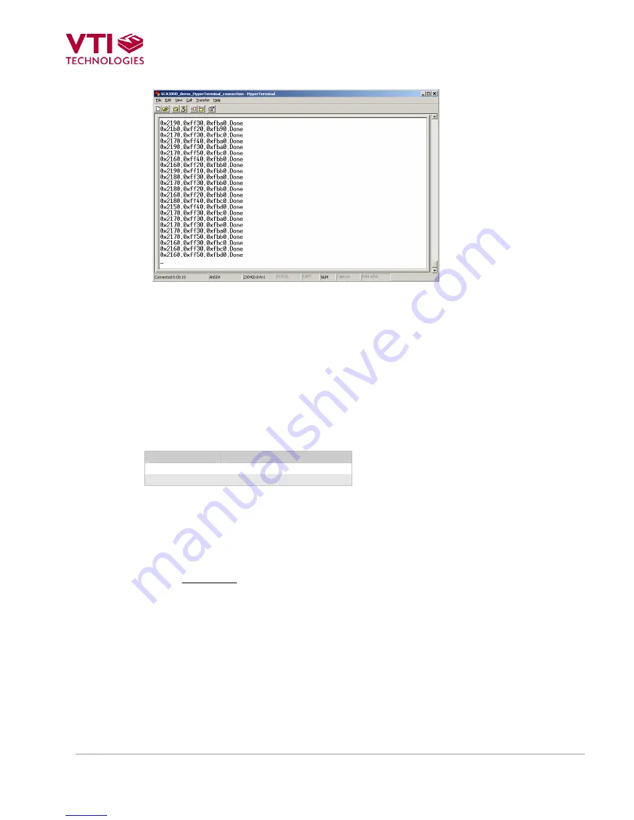
Figure 13. SCA3000 demo output during data logging.
6 CMA3000
current
consumption
measurement with DEMO KIT
The current consumption of the CMA3000 sensor can be calculated by measuring the voltage drop
over the resistor R34 (470
Ω
, 1% tolerance). Voltage drop can be measured from test points TP5
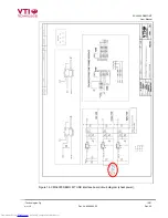
and TP6, see DEMO KIT USB interface board circuit diagram in Figure 16 (PCB design
VTI 29393 rev B0).
The offset current consumption of the DEMO KIT hardware depends on used serial communication
(SPI vs. I
2
C). The offset current consumption according to serial communication type is presented
in Table 3 below.
Table 3. Offset current consumption of the CMA3000 DEMO KIT HW.
Serial interface
Offset current consumption
SPI
~950 µA (
V
offset
= 444 mV)
I
2
C
~200 µA (
V
offset
= 94 mV)
The offset current consumption can also be measured by measuring the voltage drop over the
resistor R34 (TP5 and TP6, see Figure 16) when CMA3000 PWB is not connected to USB
interface board.
SCA3000 current consumption can be calculated
,
470
⎟⎟
⎠
⎞
⎜⎜
⎝
⎛
Ω
−
=
offset
drop
V
V
Idd
(1)
where
V
drop
is the measured voltage drop in [V] (from TP5 to TP6, see Figure 16),
V
offset
is the
measured offset current consumption (from TP5 to TP6, see Figure 16), alternatively the values
from Table 3 can be used.
Idd
is the CMA3000 current consumption in [A].
The difference in offset current consumption is due the pull up resistor in SCK/SCL line (R2 in
Figure 15). When using SPI-bus, the MCU software drives the SCK/SCL line low when there is no
communication, which results in increase in DEMO KIT offset current consumption (current through
resistor R2 in Figure 15 from DVDD to GND). When I
2
C is used, the MCU releases the SCK/SCL
line when there is no communication.
VTI Technologies Oy
12/21
www.vti.fi Doc.Nr.
8288400.02 Rev.0.2
electronic components distributor


