IT-85 Integrated amplifier
Owner’s Manual
VTL
6
•
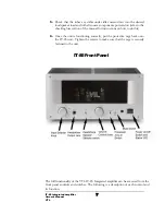
The VTL IT-85 Integrated amplifier
•
A power cord for the electrical system in your country.
•
The remote control hand-held unit
•
This User Manual, VTL Quality Assurance and test documents, VTL product
warranty registration card
Remove each item from its packaging material and check to make sure that no physical
damage has occurred during shipping of the unit. There should be no rattles inside
either of the IT-85 or remote control units. Look through the vent slots and check to
see that the tubes appear properly seated firmly in their sockets. Contact your VTL
dealer immediately if physical damage is detected.
Check for tube placement
Use the following procedures to check whether the tubes standing on the deck of your
IT-85 are placed firmly in their sockets, as the tubes can become dislodged and loosen
during shipping of the IT-85.
Visually inspect through the vent holes to ensure that all tubes are fully seated before
powering the unit on for the first time. If there are any tubes not fully seated then you
should refer to your VTL dealer, and take this procedure with the unit.
Notes for the servicing/installing technician:
1.
R
emove the protective wire cage on the top deck of the IT-85. The cage is
mounted with two screws on each side of the IT-85. Loosen the screws
and lift the wire cage slowly and carefully. Do not let the cage touch or hit
any of the tubes inside the IT-85. Keep the cage and the screws in a
separate place while you’re working on the IT-85.
2.
Make sure that the IT-85 is not connected to the power outlet and not
turned on. Use your fingers to hold onto the upper portion of the tube
towards its tip. Gently rock the side of the tube to see if there is any
movement in the tube. If there is any movement that means the tube has
come loose. Press the tube firmly into its socket, using a gentle force and
a slight “rocking” motion.
3.
Repeat the above procedure for the rest of the tubes. There are a total of
four output tubes and six input tubes in the VTL IT-85 integrated
amplifier.
4.
Proceed to the connection and power up steps in this manual, watching
for any unusual glow in the tubes when powering up for the first time.
Summary of Contents for IT-85
Page 1: ...VTL IT 85 Integrated amplifier Owner sManual ...
Page 3: ......

