IT-85 Integrated amplifier
Owner’s Manual
VTL
22
the VTL IT-85 Integrated amplifier.
For checking the bias you should take the unit and this procedure to your authorized
VTL dealer and ask them to check the bias for you
.
Notes for the service/installing technician:
Bias measurements are preferably taken with a digital multimeter equipped with the
auto-ranging feature. If you don’t have such a meter you can purchase one at a local
electronics supply store such as Radio Shack. The Radio Shack catalog numbers for
usable multimeters are 22-166, 22-167, 22-163, 22-174 or even 22-179.
Use the following procedures to measure and adjust the bias setting:
1.
Make sure that the IT-85 is
powered
off
. Remove the protective metal
cage of the IT-85, and make sure that there is sufficient room around the
unit for you to access the bias measurement points at the back edge of the
IT-85. Set the multimeter for resistance measurement (ohms). (Consult
the owner’s manual of the multimeter to make sure that you have used the
correct settings.)
2.
Connect the negative (black, “-“) probe from the multimeter to the ground
point on the IT-85or the negative (“-“) speaker binding post of the
amplifier.
3.
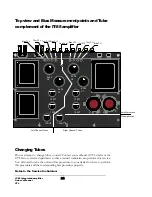
Consult the following figure for the locations of the bias measurement
points on the IT-85’s top deck. Insert the positive (red, “+”) probe of the
multimeter into each bias measurement point. The resistance reading on
each point should be 10 ohms, within a 10% range. If the resistance
reading is outside the acceptable range, please consult the VTL factory
customer service department immediately. Repeat the measurement
procedure for all 4 bias measurement points.
4.
Remove the multimeter probes from the IT-85. Check to make sure that
the IT-85 is connected to a loudspeaker or a load resistor. Power on the
IT-85 and let it warm up for about 10-15 minutes so that the tubes
become stabilized. Either short the input or put the IT-85 in the mute
state (or turn the volume down) to make sure that no signal is coming
from the preIT-85 section.
5.
Change the meter setting to measure DC voltage. Insert the negative
probe (black) from the multimeter into the ground point on the IT-85 or
the negative speaker binding post of the IT-85 fitting it into the post
where the speaker cable is connected. Insert the positive probe into the
bias measurement point of each tube going from the #1 point to #4. The
Summary of Contents for IT-85
Page 1: ...VTL IT 85 Integrated amplifier Owner sManual ...
Page 3: ......

