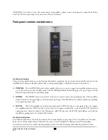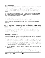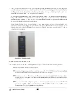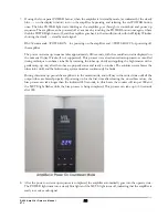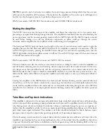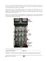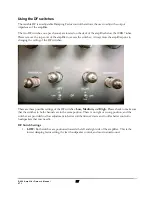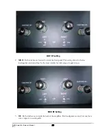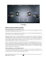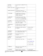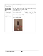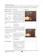
serious enough to require immediate automatic amplifier shut down. The five text indicators and their meanings
are as follows:
INVERT
(Steady red): Indicates the phase status of amplifier, as set by the rear PHASE toggle switch.
The INVERT indicator is off when the input signal is PHASE 0 (normal) and the
INVERT
indicator
turns red when the PHASE switch is set to Phase 180 position.
TUBE
(Steady green): Indicates a non-critical tube fault in the tube whose number is indicated on the
display. The amplifier continues its current operation.
TUBE
(Flashing red): Indicates a critical tube fault in the tube indicated on the display, requiring
immediate shut down of the amplifier, and not allowing re-power until the tube is changed and the fault
is reset.
HEAT
(Flashing red): Indicates amplifier overheating due to high sustained power or insufficient
ventilation, requiring immediate shut down of amplifier, and not allowing re-power until the amplifier
cools and the fault clears.
POWER
(Flashing or steady red, depending upon fault): Indicates either internal or external power
supply fault, requiring immediate shut down of amplifier. Steady red means that re-power is allowed, and
flashing red means that re-power is not allowed until the fault clears (or is reset, depending upon fault
type.)
See the Fault Indication section for a complete description of these fault indicators.
AC Voltage Setting
This component has been preset to the correct AC voltage for the country where purchased, and is not user or field re-
settable. The voltage setting is marked on the serial number badge located on the rear panel of the amplifier. If the
marking has been defaced or removed then contact the factory before connecting this component to any AC voltage
source.
WARNING: Check to make sure that the voltage setting is correct for your local voltage
rating before plugging in and turning on the amplifier, as unsafe conditions could be
created with incorrect voltages, and damage to the amplifier can result. Damage resulting
from improper voltages is not covered under the warranty.
However damage to this amplifier is unlikely, as it is as well protected as possible against operation at incorrect AC
voltages, with automatic sensing of the incoming AC voltage and programmed capability to automatically shut down
under adverse AC voltage conditions. An internal universal switching supply powers the master processor, which will
operate at any input voltage between 85VAC and 260VAC, allowing the master processor to sense the incoming AC
voltage and compare it to the internally preset AC voltage setting. If the amplifier’s preset voltage range does not match
the AC line voltage, the amplifier will not go through the power up sequence, and if powered up then the amplifier will
automatically shut down and the front panel display will flash the numeric voltage that the amplifier is set for.
Please contact your authorized VTL dealer or the VTL factory if the AC voltage is flashing on the front panel display.
S-400 Amplifier Owner’s Manual
VTL
19

