background image


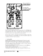
Plugging in a new tube 

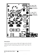
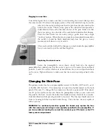
Consult the figure above to make sure that you are inserting the correct tube type into 
the correct socket.  Hold onto the upper portion of the tube towards its tip. Lower the 

tube onto the socket, making sure that the pins from the tube matches the 
holes in the socket.  There are two pins on the tube which are spaced at a 
wider distance from each other than the rest of the pins.  Make sure that 
these two pins go into the side of the socket which matches that distance.  
Press the tube firmly into its socket, using a gentle force and a slight 
“rocking” motion.  When the tube is properly and completely inserted into 
the socket it should be firmly implanted and does not give in to any 
movement at all when you try to rock it. 

After you’re satisfied with all the changes you made inside the preamplifier 
box you are ready to put the unit back together. 


Replacing the chassis cover 

Lower the preamplifier’s cover chassis slowly back into the opened 

preamplifier box, making sure that the cover is put on in the correct front and back 
position.  Locate the screws which were removed from the cover and put them back 
on the cover.  Tighten all screws to make sure that the cover is securely put back to the 
unit.  


Changing the Main Fuse 

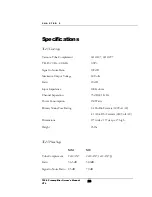
The primary mains fuse for your preamplifier is rated 1A Slo Blo (120Volt AC) or .41 
A Slo Blo (240 Volt AC).  The mains fuse is housed in a holder located on the back 
panel of the unit.  To change the fuse make sure the unit is powered off.  Disconnect 
the AC power cord from the unit.  Move the preamplifier so that you can work with 
the panel in the back.  Locate the mains fuse holder and turn the knob in a counter-
clockwise direction while pressing inwards to loosen it.  The fuse cap should come out 
from its housing with the fuse held inside the cap.  Take the fuse out and  replace it 
with a new one.   

WARNING: For continued protection against fire hazard only replace the fuse 
with the same type and rating as was originally specified for the preamplifier.  If 
you have problems locating the correct fuse contact your VTL dealer or the VTL 
factory service department. 

TL2.5 Preamplifier Owner’s Manual 
VTL 

19

Summary of Contents for TL2.5

Page 1: ...VTL TL2 5 Line Stage Preamplifier Owner sManual...

Page 2: ...ced or transmitted in any form or by any means electronic or mechanical for any purpose without the express written permission by VTL Version History Version 5 0 March 24 2009 Part Number OM 0490 Copy...

Page 3: ......

Page 4: ...the Preamplifier with the Remote Control 9 Powering the system off 10 CHAPTER 3 11 OPERATING THE PREAMPLIFIER 11 Connecting and Selecting Source Components 11 Power On Stages 11 Connecting the TL2 5 t...

Page 5: ...CHAPTER 6 24 WARRANTY 24 APPENDIX 25 Warranty Registration 25 Service Notes 25 TL2 5 Preamplifier Owner s Manual VTL ii...

Page 6: ...erience that is the most alive and the truest to your source and we hope you ll get many hours of enjoyment from it Electrical Safety Notice Electrical voltage from power cables is hazardous We recomm...

Page 7: ...Tiptoes or other isolation accessories may prove useful in reducing mechanical vibrations Do not place the preamplifier next to heat sources such as radiators stoves or other appliances Do not place...

Page 8: ...ration card Remove each item from its packaging material and check to make sure that no physical damage has occurred during shipping of the unit There should be no rattles inside either of the preampl...

Page 9: ...r audio video system to the surround processor when the switch is turned to the Processor In position In this mode the surround system will only control all of the channels of your system and the prea...

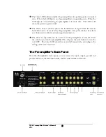
Page 10: ...amplifier s Back Panel From the Preamplifier s back panel you can access the input output ground and power connectors the main fuse holder and the serial number of the unit GND Left Right Manufactured...

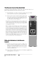
Page 11: ...emote control unit there is a delay of a few seconds about 1 2 seconds before the TL2 5 s completes the processing of the signal sent by the remote Wait for the response from the TL2 5 before pressing...

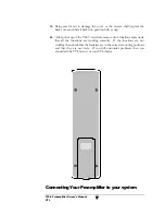
Page 12: ...ontrol functions and ensure that all the functions are working correctly If the functions are not working then check that the batteries are in the correct mounting positions and that they are not stal...

Page 13: ...amplifiers can be connected to the system The second pair can either be used for bi amping or to drive a subwoofer in the system When connecting more than one pair of amplifiers in parallel it is advi...

Page 14: ...behave as described above check to make sure that the power cable is securely connected to the AC Power connector in the back panel of the preamplifier and that the power cable is plugged into the AC...

Page 15: ...the system out of mute mode On the other hand pressing the volume down arrow will not affect the mute operating state of the preamplifier Powering the system off 1 When you re done listening to your s...

Page 16: ...or Power On Stages When you first power on your preamplifier it goes through a warm up stage which takes approximately 50 seconds During this period the preamplifier is in the muted mode as indicated...

Page 17: ...ht come through Caution If you do not have a surround processor connected to the TL2 5 s Processor In input you may get a slight buzzing sound when you set the Processor switch to the up position whic...

Page 18: ...nstallation instructions on this mode of usage Your dealer should also be able to give you guidance with this procedure Connecting to the Turntable If your TL2 5 Preamplifier is equipped with the opti...

Page 19: ...ews in a safe place so that you can put the cover back onto the unit when you have completed the following installation Check to make sure that the optional phono PC board is installed to the left of...

Page 20: ...across pins 3 and 4 and pins 8 and 9 respectively 4 Replace the cover Put the cover of the preamplifier back onto the unit and insert and tighten all 10 screws 5 Connecting the turntable to the preamp...

Page 21: ...our VTL preamplifier has been designed to ensure long tube life Tube replacement need not be considered until after approximately 5000 hours of use roughly 4 to 5 years depending on your listening req...

Page 22: ...H YOUR FINGERS OR WITH ANY METALLIC OBJECT UNTIL AFTER THE UNIT HAS BEEN SAFELY DISCHARGED The VTL preamplifiers can store energy in the power supplies long after they have been turned off and incorre...

Page 23: ...EEN C10 C3 C4 U101 U102 R112 R108 R109 R107 C11A C102 C10A C2 C103 R113 B GND B FILA GND FILA R110 R13 C104 R10 RGND RIGHT OUT LEFT RIGHT C6 C106A QC TEST PCBA 320 0805 200 PCB 360 0804 200 VER 4 0 V1...

Page 24: ...lifier box making sure that the cover is put on in the correct front and back position Locate the screws which were removed from the cover and put them back on the cover Tighten all screws to make sur...

Page 25: ...er unit which decodes signals coming from a Phillips microcontroller chip If you own another stereo component that comes with a remote control unit using the same microcontroller chip signals transmit...

Page 26: ...Follow the procedures listed in this manual to remove the tubes and change them for new ones 6 My remote control hand held unit for the preamplifier is not working What should I do Look at the back of...

Page 27: ...service department to report this problem as we are interested in knowing which models of stereo equipment could cause this problem 8 My remote control hand held unit for the TL2 5 is not working Wha...

Page 28: ...put Impedance 100K ohms Channel Separation 75 dB 1 KHz Power Consumption 150 Watts Primary Mains Fuse Rating 1A Slo Blo Ceramic 120Volt AC 41 A Slo Blo Ceramic 240 Volt AC Dimensions 19 wide x 15 deep...

Page 29: ...rding of the serial number of the preamplifier on your warranty registration card and mailing it with your purchase receipt to VTL If a VTL product fails to perform properly under the above warranty t...

Page 30: ...t Suite 10 Chino CA 91710 USA To help you keep a record of the serial number and purchase information please enter the following information into this manual Product Model Number _____________________...

Reviews: