background image


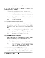
the back cover on and tighten the four screws, and test the remote unit to see if it 
is working properly. 

If the remote control unit is still not functioning properly, contact your VTL 
authorized dealer or the VTL factory service department. 


TL6.5 Preamplifier Owner’s Manual 
VTL 

47 


Summary of Contents for TL6.5

Page 1: ...VTL TL6 5 Signature Line Stage Preamplifier Owner sManual...

Page 2: ...reproduced or transmitted in any form or by any means electronic or mechanical for any purpose without the express written permission by VTL Version History Version 2 2 November 2007 Part Number OM 6...

Page 3: ......

Page 4: ...to your system 15 Connecting to a Turntable 15 Select and Connect Source Components 15 Connecting a second pair of amplifiers 16 Connecting the TL 6 5 to a Home Theater System 17 Using the TL 6 5 to...

Page 5: ...ge and Power Supply Protection Fuses 43 Cleaning 44 Troubleshooting 45 CHAPTER 5 48 TL 6 5 SPECIFICATIONS 48 CHAPTER 6 49 WARRANTY 49 APPENDIX 51 Warranty Registration 51 Service Notes 51 TL6 5 Preamp...

Page 6: ...ly represents a fresh breakthrough in furthering the refinement of the VTL sound and the ability of the new TL 6 5 to articulate and present the listener with a broad cohesive picture of the total mus...

Page 7: ...y been able to significantly improve upon the highly regarded TL5 5 sound By coupling this technology to multiple super regulated power supplies we have dramatically improved on the preamplifier s cap...

Page 8: ...ior to connecting this preamplifier to any audio or video equipment in your system make sure this unit s power and the rest of the equipment connected to its input and output channels is turned off Ad...

Page 9: ...stoves or other appliances Do not place the preamplifier where small children might be able to tamper with the equipment If it is not possible to place the preamplifier out of the reach of small child...

Page 10: ...heavy and awkward to lift with the weight unevenly distributed and you should not attempt to move the unit without help The TL 6 5 Preamplifier weighs approximately 50 lbs 22 72 Kg Do not exceed fuse...

Page 11: ...SAVE THE CARTON AND ALL PACKAGING FOR ANY FUTURE SHIPMENT OF THE TL 6 5 After you open the carton you should find the following items inside The preamplifier 1 standard power cord for the electrical...

Page 12: ...unit If your CD player has balanced out connect the cable from the balanced output of your CD player to the CD1 balanced input of your TL 6 5 preamplifier matching the left and right channels Make sur...

Page 13: ...t selection of CD1 is in balanced mode If your Source component is setup in balanced mode you are now ready to play your music Turn the volume to the appropriate level by rotating the Volume Control k...

Page 14: ...s applied to the inputs the unit must be configured for balanced operation and vice versa 3 The Tape 1 and Tape 2 inputs are also usable as normal single ended only inputs with the additional capabili...

Page 15: ...egree of out of balance The display automatically reverts to volume readout a few seconds after release of the Balance button c The Mute button is to allow you to switch the preamplifier into the mute...

Page 16: ...into standby mode Press up for on and down for off The Trigger Outputs provide a 12V DC signal to external components that are to remotely power up after the preamplifier is operational Connect the po...

Page 17: ...e Remote Control hand held unit supplied with this preamplifier allows the user to perform the following functions Power the preamplifier on and off This is a toggle control which changes the state fr...

Page 18: ...e of or in addition to the supplied remote wand There are additional discrete remote codes available that are programmed into the preamplifier to replace the three toggle commands that are used on the...

Page 19: ...that the voltage setting on your TL 6 5 is correct for your local voltage rating before plugging in and turning on your TL 6 5 Power Source for the VTL TL 6 5 Preamplifier Your TL 6 5 Preamplifier is...

Page 20: ...king any connections to the preamplifier make sure that the preamplifier and the source components are powered off Connect the output cables from each of the source components to the relevant inputs o...

Page 21: ...ifier to the left and right outputs of the preamplifier The ultra low output impedance of the preamplifier is easily capable of supporting long interconnects up to 35 feet or longer and can also easil...

Page 22: ...6 5 receives the external surround processor s signal for the front left and right channels directly from the external surround processor and passes it directly to the power amplifiers at the same le...

Page 23: ...ll be a custom length and will include the correct connector for the device to be triggered The dimensions of the connector in mm are The polarity of the trigger voltage is positive on the pin closest...

Page 24: ...warm up stage that takes approximately 90 seconds with countdown status displayed on the front panel numeric display window During this warm up period the preamplifier is in the muted mode After the w...

Page 25: ...ard through the speakers as the volume control is rotated with a 3 step clicking noise sometimes heard between volume steps 19 20 38 39 57 58 and 76 77 This clicking noise is a normal function of the...

Page 26: ...em is in phase correct mode click the Phase button once to put it into phase inverted mode The Phase LED will turn from off to red when the system is changed to phase invert 7 Use the remote control s...

Page 27: ...power up Loss of power before the settings are saved will cause the settings to be lost from memory and the preamplifier will have to be programmed again and the settings saved by powering down from t...

Page 28: ...input to Unity Gain for any input CD1 Aux While the preamp is in operate mode select the input you wish to set to Unity Gain Then hold the Mon Proc button and at the same time press the input button...

Page 29: ...old the Mon Proc button and press the Power button on the front panel and release the MON Proc button after pressing the Power button Restore Programming Mode Remove the Lock out mode to enable Trigge...

Page 30: ...ence neither LED is lit After power up and trigger sequence if Tape 1 is selected as input LED will turn green If Tape monitor is selected after power up and trigger sequence LED will turn red When Ta...

Page 31: ...lance display is not suppressed If the balance display is suppressed then the indicators are only lit when accessing balance function Indicates input offset with bar on left of numerals for negative o...

Page 32: ...splay changes to 00 When the unit has completed the power up sequence the numeric display changes to volume indicator to indicate that unit is now ready to play and the volume readout shows 00 The fro...

Page 33: ...tely power on other components in the system such as power amplifiers which are turned on after the preamplifier is warmed up Trigger outputs are typically 12 Volt systems connected via hardwired conn...

Page 34: ...properly configured for the correct mode of operation If a balanced signal is applied to the inputs the unit must be configured for balanced operation and vice versa User input User holds down the inp...

Page 35: ...ffset Addressable through RS 232 port also see specific section for command structure Indication Volume display changes to display that input offset level while input button is held down If offset lev...

Page 36: ...he input that is in unity gain mode the mute function is turned on again and the mute LED blinks User has to explicitly un mute to use that input If there is no reaction to the unity command indicatin...

Page 37: ...a two digit number to indicate the present volume level As volume level is changed the front panel display increments sequentially to display the new volume setting The volume level ranges from 00 to...

Page 38: ...CE button is released the numerical display returns to indicating the volume setting and depending upon user setting out of balance direction bar is either displayed or suppressed for out of balance s...

Page 39: ...h to correct the problem by changing the phase of the signal User input User depresses Phase button on front panel or remote or sends a discrete phase or phase reverse signal from external remote Indi...

Page 40: ...he change User input User presses front panel Power button while holding Mon Proc button down Addressable through RS 232 port also see specific section for command structure Indication No indication S...

Page 41: ...es to bypass toggle commands for Crestron AMX or Pronto Use standard user wand with temporary internal jumper for some extra codes from 4 extra positions on remote key matrix Mute ON Mute OFF and Powe...

Page 42: ...and parameter with meaning required parameters and meaning optional parameters For systems without a return button the amplifier s microprocessor recognizes C as a carriage return and R as a return Th...

Page 43: ...decrements and outputs the new balance setting to the RS 232 port PHASE 0 180 For querying or setting the phase setting of the amplifier Returns current phase setting FADE For lowering volume setting...

Page 44: ...OUNTDN ON OFF For toggling between muting and unmuting the power up countdown Returns current countdown status DSPLYOFF n For automatically turning off the display after last command after programmed...

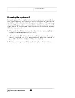
Page 45: ...wer amplifiers off the preamplifier will power down in a muted state and no damage will be done to your system 1 When you re done listening to your system always turn your power amplifier s off first...

Page 46: ...age beyond their peak performance there will be a general softening of the sound We recommend a complete replacement of both tubes in your preamplifier at that time which will restore it to a like ne...

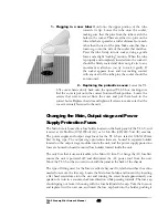
Page 47: ...total of two tubes both 12AU7 The following figure indicates the location of the tube type with respect to the sockets looking from above and in front of the chassis 1 Diagnose the tubes If you are n...

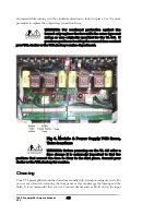
Page 48: ...Main Output stage and Power Supply Protection Fuses The Main fuse is housed in a fuse holder located on the back panel of the TL 6 5 and is rated at 2A Slo Blo 100 120Volt AC or 1A Slo Blo 220 240 Vol...

Page 49: ...vice department Fig 4 Module Power Supply PCB fuses Tube locations WARNING Before powering on the TL 6 5 after a fuse change it is extremely important to find the problem that caused the fuse to blow...

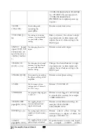
Page 50: ...receiver unit that decodes signals coming from a proprietary micro controller code set that is based on the Phillips RC5 code set If you own another stereo component that comes with a remote control u...

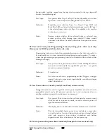
Page 51: ...ut still I get no sound What is the problem There are protection fuses mounted on the output stages of the TL 6 5 preamplifier that will open to protect the circuit if the outputs are accidentally sho...

Page 52: ...screws and test the remote unit to see if it is working properly If the remote control unit is still not functioning properly contact your VTL authorized dealer or the VTL factory service department T...

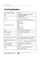
Page 53: ...Fade Balance Control Phase Reverse Gain 14 dB single ended 20dB balanced Output Impedance 25 Ohms Max 195 ohms at 10Hz Input Impedance 50K Ohms Frequency response 0 1 dB 1 Hz 200KHz into 20Hz 100kHz...

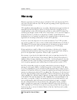
Page 54: ...e the unit was purchased and by VTL Amplifiers Inc Under the terms of the warranty defective parts will be repaired or replaced without charge excepting the cost of tubes A six month warranty on tubes...

Page 55: ...may only be registered with the VTL distributor in the country of purchase In the case of returns from outside the USA the owner of the product returned is responsible for all shipping charges and VTL...

Page 56: ...t Suite 10 Chino CA 91710 USA To help you keep a record of the serial number and purchase information please enter the following information into this manual Product Model Number _____________________...

Reviews: