15
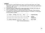
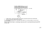
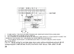
NOTES:
1. When used in a single-transformer system, leave the metal jumper wire in place
between RC and R. If used on a two-transformer system, remove the metal jumper
wire between RC and R.
2. If the thermostat is configured for a heat pump system, configure the changeover
valve for energized on cool or heat in the Installer setup.
3. The L terminal is an input for optional system alarm monitoring. If the terminal is
connected to 24V, ES (emergency signal) will appear on the screen, overriding the
room temperature display.
Fig.6.Terminal identifications.
Summary of Contents for LAKEPRO-1
Page 1: ...LAKEPRO 1 WI FI TOUCHSCREEN PROGRAMMABLE THERMOSTAT...
Page 4: ......
Page 11: ...7 Fig 2 Lakepro 1 rear dimensions in inches mm...
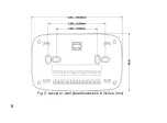
Page 12: ...8 Fig 3 Lakepro 1 wall plate dimensions in inches mm...
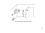
Page 13: ...9 Fig 4 Selecting the thermostat location...
Page 16: ...12 Fig 5 Mounting wall plate...
Page 20: ...16 Fig 7 Inserting wires in terminal block IMPORTANT Use 18 gauge thermostat wire...
Page 68: ...64 Fig 36 Fig 37 6 Wait for the thermostat to be added successfully You may have to press Done...
Page 83: ......


