background image

Information furnished by VubIQ is believed to be accurate and reliable. However, no responsibility is assumed by VubIQ for its use, nor for any infringements of patents or 

other rights of third parties that may result from its use. Specifications subject to change without notice. No license is granted by implication or otherwise under any patent 

or patent rights of VubIQ. Trademarks and registered trademarks are the property of their respective owners. 

VuTxWGM3.7.02.13

VubIQ, Inc.               

+1-949-226-7185              sales@vubiq.com 


9231 Irvine Blvd, Irvine, California 92618 USA      www.vubiq.com

2

Data Sheets / Software

Data sheets for the Development System and the TX/RX waveguide modules are available at:

www.vubiq.com

The specific links are: 

User Guide (this document):   


http://vubiq.com/pdf/DevelopmentSystem_UserGuide.pdf

Development System GUI (1.90): 


http://vubiq.com/files/VubiqGUI.zip

TX Waveguide Module (V60TXWG3):  

http://vubiq.com/pdf/TxWaveguideModuleDataSheet.pdf

RX Waveguide Module (V60RXWG3):  

http://vubiq.com/pdf/RxWaveguideModuleDataSheet.pdf

Summary of Contents for V60WGD03

Page 1: ...esult from its use Specifications subject to change without notice No license is granted by implication or otherwise under any patent or patent rights of VubIQ Trademarks and registered trademarks are the property of their respective owners VuTxWGM3 7 02 13 VubIQ Inc 1 949 226 7185 sales vubiq com 9231 Irvine Blvd Irvine California 92618 USA www vubiq com 1 60 GHz Tx Rx Development System V60WGD03...

Page 2: ...s are the property of their respective owners VuTxWGM3 7 02 13 VubIQ Inc 1 949 226 7185 sales vubiq com 9231 Irvine Blvd Irvine California 92618 USA www vubiq com 2 Data Sheets Software Data sheets for the Development System and the TX RX waveguide modules are available at www vubiq com The specific links are User Guide this document http vubiq com pdf DevelopmentSystem_UserGuide pdf Development S...

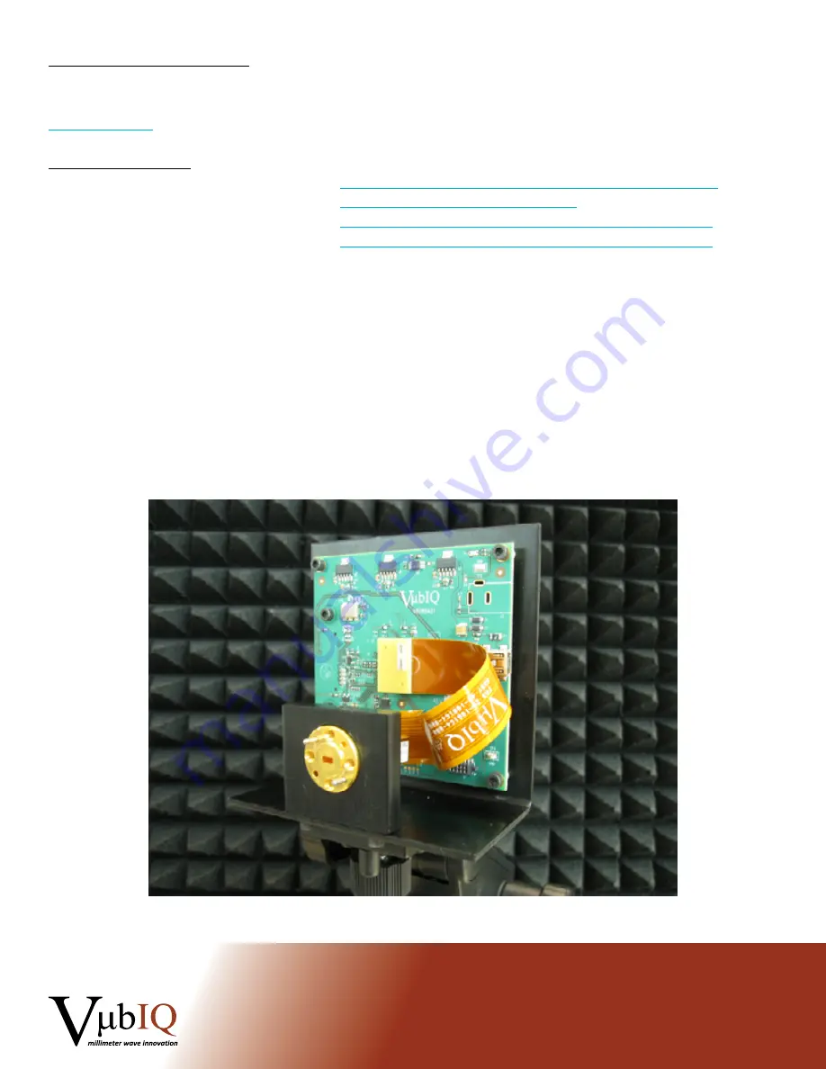
Page 3: ...rview Waveguide Module Board Assembly on Tripod International Unlicensed Spectrum Allocation for the 60 GHz Band Potential applications range from multi gigabit communications systems such as GigE wireless LAN 802 15 3c 802 11ad development SDI video products radar and radiometery The 60 GHz spectrum is now allocated as unlicensed in many countries world wide The V60WGD03 development system is com...

Page 4: ...7185 sales vubiq com 9231 Irvine Blvd Irvine California 92618 USA www vubiq com 4 2 0 Development System Contents Transmitter Waveguide Module V60TXWG3 Receiver Waveguide Module V60RXWG3 Transmitter board 1 Receiver board 1 Board waveguide module mounting bracket 2 Bench top tripod 2 USB cable 2 GUI software downloadable from web site Documentation and data sheets downloadable from web site MCX co...

Page 5: ... software using USB as the interface Each board derives its power from the USB connection standard operation The control processor on each board communicates with the PC through the USB port Baseband signals are connected via the high speed baseband connector on the rear side of each board The baseband connector is a Samtec QSE The mating connector required is a Samtec QTE 020 01 L D A The expansi...

Page 6: ... coaxial connectors For higher level system integration direct connection via the Samtec high speed connector can be facilitated using the mating Samtec connector as shown A typical test set up is shown in Figure 3 below Here the transmitter baseband source is either a user designed baseband system or a programmable arbitrary waveform generator AWG A two channel AWG can create any form of vector m...

Page 7: ...set up and controlled from a host PC running the GUI software The software can be downloaded from our web site http www vubiq com customerdownloads php as a ZIP file Unzip the files and place into a convenient directory on the PC that will be used with the development system test setup With a transmitter and receiver board connected via the USB cables to the PC run the software VubiqGUI exe A tran...

Page 8: ...that may result from its use Specifications subject to change without notice No license is granted by implication or otherwise under any patent or patent rights of VubIQ Trademarks and registered trademarks are the property of their respective owners VuTxWGM3 7 02 13 VubIQ Inc 1 949 226 7185 sales vubiq com 9231 Irvine Blvd Irvine California 92618 USA www vubiq com 8 Figure 4 Transmitter GUI Windo...

Page 9: ... that may result from its use Specifications subject to change without notice No license is granted by implication or otherwise under any patent or patent rights of VubIQ Trademarks and registered trademarks are the property of their respective owners VuTxWGM3 7 02 13 VubIQ Inc 1 949 226 7185 sales vubiq com 9231 Irvine Blvd Irvine California 92618 USA www vubiq com 9 Figure 5 Receiver GUI Window ...

Page 10: ...xWGM3 7 02 13 VubIQ Inc 1 949 226 7185 sales vubiq com 9231 Irvine Blvd Irvine California 92618 USA www vubiq com 10 The window layouts are designed as intuitive block diagrams of the transmitter and receiver waveguide module circuits There are separate boxes for control and monitoring functions The following chart Figure 6 shows the transmitter and receiver functions for each box Figure 6 The win...

Page 11: ...vd Irvine California 92618 USA www vubiq com 11 The Temperature Synth box monitors the board temperature and the RF module temperature in ºC The synth status section indicates the synthesizer lock status and the band tuning status Power supply voltages are monitored in this box Note the 5 volt supply is measured from the USB source and typically runs at about 4 1 to 4 4 V The Control box RX shown ...

Page 12: ...ule s operating frequency is set with the Synth Freq box shown above This control sets the synthesizer digital divisor ratio in the RF module The standard frequency range can be set from 57 24 GHz to 64 80 GHz in 0 54 GHz steps Optionally the RF modules can be set from 57 0 GHz to 64 0 GHz in 0 5 GHz steps with a reference oscillator clock of 285 714 MHz The synth frequency box has pre configured ...

Page 13: ...ximum The slider control or drop down menu can be used there are 16 settings from 0 dB to 20 dB The IF Filter Q box is a coarse IF bandwidth control providing highest Q narrowest bandwidth at 800 MHz and lowest Q widest bandwidth at 1 2 GHz There are 5 settings from 800 MHz to 1 2 GHz The AM I Channel control box RX only selects the I channel demodulator default or the AM detector When the AM dete...

Page 14: ...s used to set the gain of the baseband amplifiers The lower the attenuation level in dB the higher the gain setting When this control is set to 0 0 dB the baseband gain is at maximum The slider control or drop down menu can be used there are 7 settings from 0 dB to 36 dB There are two attenuators for fine gain adjustment of the I and Q channels the I Atten Fine and Q Atten Fine boxes RX only These...

Page 15: ... the on board oscillator is 308 571 MHz 540 MHz channel spacing and has a stability rating over temperature of 25 ppm There may be certain system level applications that require the transmitter and or receiver to be phase locked to an external source Also if 500 MHz channel spacing is desired the external reference clock must be 285 714 MHz The TX RX RF boards are set up to provide the following o...

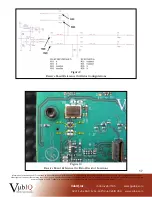
Page 16: ...ject to change without notice No license is granted by implication or otherwise under any patent or patent rights of VubIQ Trademarks and registered trademarks are the property of their respective owners VuTxWGM3 7 02 13 VubIQ Inc 1 949 226 7185 sales vubiq com 9231 Irvine Blvd Irvine California 92618 USA www vubiq com 16 Figure 7 Transmit Board Reference Oscillator Configurations Figure 8 Transmi...

Page 17: ...bject to change without notice No license is granted by implication or otherwise under any patent or patent rights of VubIQ Trademarks and registered trademarks are the property of their respective owners VuTxWGM3 7 02 13 VubIQ Inc 1 949 226 7185 sales vubiq com 9231 Irvine Blvd Irvine California 92618 USA www vubiq com 17 Figure 9 Receive Board Reference Oscillator Configurations Figure 10 Receiv...

Reviews: