Information furnished by VubIQ is believed to be accurate and reliable. However, no responsibility is assumed by VubIQ for its use, nor for any infringements of patents or
other rights of third parties that may result from its use. Specifications subject to change without notice. No license is granted by implication or otherwise under any patent
or patent rights of VubIQ. Trademarks and registered trademarks are the property of their respective owners.
VuTxWGM3.7.02.13
VubIQ, Inc.
+1-949-226-7185 sales@vubiq.com
9231 Irvine Blvd, Irvine, California 92618 USA www.vubiq.com
6
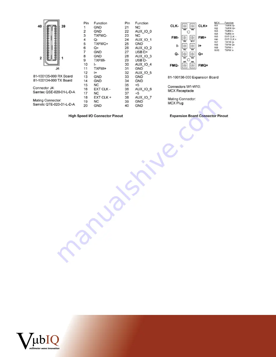
Figure 2
Baseband High Speed Connector and Expansion Board Connectors
Figure 2 shows the pinout of the high speed baseband connector and the expansion board coaxial connectors.
For higher level system integration, direct connection via the Samtec high speed connector can be facilitated
using the mating Samtec connector as shown.
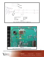
A typical test set up is shown in Figure 3 below. Here the transmitter baseband source is either a user designed
baseband system, or a programmable arbitrary waveform generator (AWG). A two channel AWG can create any
form of vector modulation (I and Q baseband) with appropriate programming or selectable standard modulation
formats (such as BPSK, QPSK, etc.). The receiver baseband scheme is again either user defined or a signal
analysis test system.
By using a programmable AWG for the transmitter baseband source, user defined vector modulation schemes
can be created along with various error correction coding, equalization testing, etc. Most AWG products
available today work with MATLAB and other tools that provide a convenient method of baseband signal
generation.


