background image

should always be parallel to the cutting disk.   The adjustment of the 
guide should always be monitored, using the cut-width scales (

12

) on 

the surface of the workbench (

8

).

ź

In  the  event  of  mounting  the  guide  on  the  other  side  of  the 

workbench, place the guide on the opposite side of the limiter rack and 
screw it down.

OPERATION:

Prior  to  connecting  the  device  check  if  the  data  on  the  rating  plate 
conform with  the  parameters  of  the  mains. The  mains,  to  which  the 

S2 30 min: casual work, nominal work time 30 min.

cutter is connected, must be safeguarded with a 10 A fuse. 

CAUTION!

 After 30 min of work with constant load pause the work until the 

Turning on/off 

cutter cools off completely.

To switch on the cutter, press the green button «

I

» of the on/off switch 

PREPARATION FOR WORK:

(

4

). Prior to commencing work wait until the cutter reaches its maximum 

CAUTION!

 Ensure appropriate order and lighting of the work place. 

rotational speed and the coolant pump starts forcing water onto the 

Unpack the cutter and check for any transport damage. 

cutting disk.
To turn the cutter off, press the red button «

0

» of the on/off switch (

4

).

Mounting the cutter

CAUTION!

  After  each  adjustment  please  run  a  test  cutting  in  order  to 

CAUTION!

 Prior to any maintenance work, reattaching and assembly of 

confirm the new parameters.

the device make sure that the power cord is disconnected from the power 
supply.


General guidelines on cutting

Prior to mounting the cutter check the completion of the device and the 

For all types of cutting first make sure that the cutting disk does not touch 

condition and attachment of movable components (cutting disk (

20

the guides or any other parts of the device at all stages of work.

and protective screen (

10

) on the separating wedge (

11

) ): 

Ensure that all screens are properly attached. 

ź

turn the disk manually (make sure the plug is out of the mains socket) 

Protect the cutting disk from falling down or shocks. Do not apply lateral 

to check whether the drive transmission mechanism is not blocked 

force to the disk. 

and the disk is properly attached,


Operator's position

ź

the mounting nut of the protective screen on the separating wedge 

Do not stand in line with the disk in front of the device. Always stand 

should be tightened in a manner enabling the protective screen (

10

slightly to the side.

to lift when material reaches the cutting disk and return back when 


Jamming

cutting is over. 

In the event of jamming of the cutting disk, turn the cutter off, unplug it 

After checking the components the cutter and the coolant container (

14

from the power supply and remove the processed material.

should be placed firmly and screwed down to the workbench or another 


 Straight cut

stable surface. Use the mounting openings to screw down the device (

1

). 

Adjust the cut width using the parallel guide (

7

) and lock with wing bolts 

Prior  to  turning  on  please  install  the  separating  wedge  with  the 

(

5

). The width of the cut can be read using the scales (

12

). 

CAUTION:

 The 

protective screen and fill the coolant container with water (

14

) to the 

scales must be set identically on both sides of the table.

indicated level (

16

).

Fig. 

E

  demonstrates  the  appropriate  position  of  hands  for  straight 

 Adjustment of the separating wedge

cutting. The tiles should be moved with both hands. Hands should be 

CAUTION:

  The  separating  wedge  secures  the  processed  item  from 

placed away from the cutting line of the tile. 

capturing by the disk and ejecting it towards the operator. The wedge must 

The  movement  must  correspond  to  disk  cutting  capacity.  Move  the 

be installed at all times. Properly adjusted wedge should be in line with the 

processed  material  slowly  and  evenly  forward.  During  cutting  the 

disk, approx. 2-5 mm from the disk edge. 

cutting disk cannot significantly lower its rotational speed, so adjust the 

ź

In order to adjust the separating wedge (

11

), loosen the wing bolts 

pressure accordingly. After cutting the tile, turn the cutter off.

(

3

) on both sides of the workbench (

8

) and angle the workbench, so that 

CAUTION:

  Ejection  of  minor  quantities  of  water  by  the  disk  during 

the separating wedge can be placed in the holder (see: fig. 

B

). Then, 

operation is normal. The water level in the container should be monitored 

place  the  wedge  (

11

)  in  line  with  the  cutting  disk  (

20

),  adjust  the                         

on a regular basis.

2-5  mm  clearance between  the  wedge  and  the  disk  and  tighten  the 


Diagonal cut

mounting bolts (

21

), locking the wedge in this position.

CAUTION:

   When cutting using the angle guide, always use the parallel 

 Mounting the parallel guide

guide. This method is applicable only to small tiles.

The parallel guide (

7

) can be placed on both sides of the workbench (

8

).

ź

Rest the angle guide (

9

) against the parallel guide (

7

) (fig. 

F

).

ź

Mount the wing bolts (

5

) and nuts for the guide (

7

).

ź

Adjust the parallel guide (

7

) to the proper width and lock with wing 

ź

Slide the guide fixture into the stop strip (

6

) of the workbench (

8

).

bolts (

5

) on both sides of the cutter.

ź

Adjust the guide according to working requirements and screw down 

ź

Place the material in the angle guide (

9

).

the mounting bolts (

5

).

In  order  to  protect  the  processed  material  from  jamming,  the  guide 

ź

Turn the cutter on and, after reaching maximum rotational speed, 

n


n


n


n


n


n


n


n


n


7

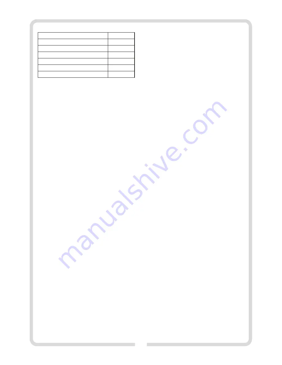
Sound pressure level 

(LpA)

                      92 dB(A)

Sound power level

 (LwA)         

                      105 dB(A)

Gross/net weight

10,0 kg / 9,6 kg

Equipment class/ Ingress protection

                              I / IP 20 

Workbench dimensions                                                      360 x 330 mm

2

Vibration level a  (K=1,5m/s ) acc. to EN 61029-1

n


2

    <

2,5 m/s


Work cycle

S2 30 min

Summary of Contents for VG18601

Page 1: ...VG18601 Oryginalna instrukcja obs ugi Instruction manual Instruc ii de folosire RO Lieto anas instrukcija LV RU PRZECINARKA DO GLAZURY GLAZE CUTTER MA IN DE T IAT GRESIE FL U GRIEZ JS 10 4 17 25 32...

Page 2: ...2 5 1 2 3 4 6 7 9 10 11 8 12 13 14 A 19 18 16 B 15 17 13 20 17...

Page 3: ...3 C 14 13 12 11 5 10 9 8 7 6 5 4 3 2 1 1 0 0 2 3 4 5 6 7 8 2 E 14 13 12 11 5 10 9 8 7 6 5 4 3 2 1 1 0 0 2 3 4 5 6 7 8 2 8 F D 8 21 11 10 3 8 9 7 7 3 3...

Page 4: ...heating radiators and refrigerators Touching earthed or grounded surfaces increases the risk of electric shock c Donotexposeyourpowertooltorainordampenvironments Waterpenetratingthetoolincreasestheri...

Page 5: ...asewithoriginaldevicesintendedforthispurpose d Donotallowthirdpartiestocomeclosetothecutterinmotion k Storepowertoolsinadry dustandwater protectedplace l Carry your power tool in its original packagin...

Page 6: ...e contradictorytotheintendeduseandshallresultinthelossofwarranty 8 Workbench For any damages or injuries resulting from such use liability shall be bornebytheuseroroperatorandnotthemanufacturer 9 Angl...

Page 7: ...reweddowntotheworkbenchoranother Straightcut stablesurface Usethemountingopeningstoscrewdownthedevice 1 Adjustthecutwidthusingtheparallelguide 7 andlockwithwingbolts Prior to turning on please install...

Page 8: ...e the proper direction of rotation of the cutting disk see arrowindicators 17 onthediamonddiskandtheprotectivescreens Mountthescreenofthecuttingdisk installthecoolantcontainerunder thescreenandscrewth...

Page 9: ...cts PROFIX code type 230V 50 Hz 600W kl I no 2950 min 180 mm meet essential requirement included into the following Directives of the European Parliament and the Council 2006 42 EC of 17 May 2006 on m...

Page 10: ...trat kontrolinadelektronarz dziem a Wtyczki elektronarz dzi musz pasowa do gniazdek Nigdy w aden spos b nie nale y przerabia wtyczki Nie nale y u ywa adnych przed u aczy w przypadku elektronarz dzi ma...

Page 11: ...s instrukcj na u ywanie elektronarz dzia Elektronarz dzia s uszkodzonelubodkszta cone niebezpiecznewr kachnieprzeszkolonychu ytkownik w b Dopilnuj eby wybrana tarcza tn ca by a odpowiednia do e Elektr...

Page 12: ...inarki os onlubtarcztn cych zg aszano zarazpoichzauwa eniu Przeno na przecinarka do p ytek ceramicznych mo e by stosowana do typowych czynno ci ci cia ma ych i rednich p ytek ceramicznych kafli glazur...

Page 13: ...ement w przecinark razem ze zbiornikiem p ynu ch odz cego 14 nale y ustawi stabilnie i przykr ci rubami do sto u Podzia ki do ustawienia szeroko ci ci cia warsztatowego lub do stabilnej podstawy Do te...

Page 14: ...ronachsto u CZYSZCZENIEIKONSERWACJA NarysunkuEjestpokazanapoprawnapozycjar kpodczaswykonywania UWAGA Przed przyst pieniem do czyszczenia i prac ci cia prostego Posuwanie p ytek musi odbywa si obiema r...

Page 15: ...niazdazasilaj cego oraz jego osprz t sk adaj si z r nych rodzaj w materia w jak np metal i tworzywa sztuczne Uszkodzone elementy urz dzenia prosz Sprawdzi dzia aniewy cznikar nicowo pr dowego dostarcz...

Page 16: ...a VULCAN Concept kod PROFIX VG18601 typ TC180C 1 230 V 50 Hz 600 W kl I no 2950 min mm 180 spe nia wymagania okre lone w dyrektywach Parlamentu Europejskiego i Rady 2006 42 WE z dnia 17 maja 2006 r w...

Page 17: ...RCD VG18601 17...

Page 18: ...18 a a...

Page 19: ...a a a a RCD 19...

Page 20: ...RCD a 1 1 1 2 1 1 180x 2 2x5 x 22 2 1 1 1 1 1 A B C D 2 3 A 1 2 3 4 5 6 7 8 9 10 11 12 13 14 B 15 16 17 18 19 20 C 21 20...

Page 21: ...5 n S2 30 30 30 n 20 10 11 10 n I 4 10 0 4 14 1 n 11 3 8 B 11 20 2 5 21 7 8 5 7 6 8 5 12 8 21 230 50 600 180 22 2 90 35 LpA 92 A LwA 105 A 10 0 9 6 I IP 20 360 x 330 2 a K 1 5 n EN 61029 1 S2 30 45 20...

Page 22: ...2 D 2 n n n 14 15 n 13 7 5 18 12 19 B 20 E 17 n n 9 7 F 7 5 9 14 9 7 n n 3 8 22...

Page 23: ...34 03 228 23 n...

Page 24: ...X VG18601 S1M ZP35 125 230 50 600 n 2950 180 mm o 2006 42 EC 17 2006 95 16 L 157 09 06 2006 24 2004 108 EC 15 2004 89 336 L 390 31 12 2004 24 37 2011 65 EU 174 1 2011 88 110 EN60745 1 2009 EN55014 1 2...

Page 25: ...e Nu folosi i cablul de alimentare la mutarea tragerea uneltei sau tragerea techerului din priz P stra i cablul de alimentare departe desursedec ldur ulei muchiiascu itesaup r i nmi care Cabluriledete...

Page 26: ...nainte de nlocuirea discului de t iere deconecta i techerul de la sarcin pentru c teva minute pentru a distribui corect prizadealimentare unsoarea nmecanismuldetransmisie AVERTISMENT Ma ina de t iat g...

Page 27: ...reghidaj 2buc referitoarelasiguran Ghidajparalel 1buc ntre inearea i repararea Ghidajunghiular 1buc a Utilizatorul trebuie s fie informat cu privire la condi iile care au Discdediamantdet iere 180x 2...

Page 28: ...r ciredisculdet iere Pentruaoprima ina ap s mbutonulro u 0 al ntrerup torului 4 n Montareama iniidet iat ATEN IE Dup fiecareschimbareaset rii recomand mexecutareaunei Aten ie Deconecta i techeruldinpr...

Page 29: ...8 sub unghiul dorit de pe scara unghiular 2 i bloca i din nou materiale cum ar fi metal i materiale plastice Elementele deteriorate uruburile fig D Ghidajul trebuie setat la o distan de aproximativ po...

Page 30: ...zat numaicudiscuridediamantdet ierecugranula ie Folosi i ntotdeaunaochelariideprotec ie Folosi i ntotdeaunaprotec ieacustic Prezenta instruc iune este protejat prin dreptul de autor Copierea nmul irea...

Page 31: ...p 230V 50 Hz 600W n 2950 min 180 mm o ndepline te sc cerin ele stabilite n directivele Parlamentului European i ale Consiliului 2006 42 CE din 17 mai 2006 privind echipamentele tehnice i de modificare...

Page 32: ...ts ar iezem t m vai ar masu savienot m da m pieaug elektrisk sstr vastriecienarisks c Nedr kst pak aut elektroinstrumentus uz lietus vai mitruma iedarb bu Gad jum ja elektroinstrument iek st dens piea...

Page 33: ...ci apgriezienu trumu Darba instruments kur grie as ar trumu j Elektroinstrumentu nepiecie ams glab t transport t liel kuparpie aujamovarsal ztunt da asat elties iepriek p rliecinoties ka visas kust g...

Page 34: ...rtne 1gab ier cesra ot jsvait servisadienesti Atdalo ais lisaraizsargp rsegu 1gab b Nepie aut dens kontaktu ar instrumenta elektrisk m Skr ves ar iek jo se st ri ar vadotnes stiprin anas uzlikt iem 2...

Page 35: ...bu un labu trumuundzes jo idrumas kniss kss kn t deniuzgriez jdisku apgaismojumu Laiizsl gtugriez junepiecie amsnospiestsl d a 4 sarkanopogu 0 Izpakotgriez juunp rbaud tiesp jamostransport anasdefektu...

Page 36: ...pakojum Iepakojums ir izejviela kuru var atk rtoti izmantot vai Fl uf z anairiesp jamanovietojotgaldusl piv lam f z anasle nodotatk rtotaip rstr dei Ier ceunt spar kojumssast vnoda diem aj nol k nepie...

Page 37: ...tikaiardimantagriez jdiskiemarpilnu uzb rumu Vienm rlietotaizsargbrilles Lietotdzirdesaizsardz basl dzek us instrukcija ir sarg ta ar autorties b m Aizliegts to kop t pavairot bez PROFIXSIA rakstiskas...

Page 38: ...ts ti marka kods PROFIX tips 230V 50 Hz 600W n 2950 min 180 mm o izpilda Eiropas Parlamenta un Padomes direkt vu pras bas noteiktas 2006 g 17 maija 2006 42 EK attiec b uz ma n m kura maina direkt vu 9...

Page 39: ...39...

Page 40: ...www profix com pl...

Reviews: