background image

ER SERIES FRYER SERVICE MANUAL SUPPLEMENT - ELECTRICAL OPERATION

F24696 (May 2001)

Page 31 of  56

Summary of Contents for 126905

Page 1: ...if you have the necessary tools instruments and skills required to perform the procedure Procedures for which you do not have the necessary tools instruments and skills should be performed by a trained Vulcan Service Technician Reproduction or other use of this Manual without the express written consent of Vulcan is prohibited 2ERD40F SHOWN SERVICE MANUAL SUPPLEMENT KLEENSCREEN SERIES ELECTRIC FRY...

Page 2: ...lid State Fryer Control Full Vat 9 Computer Control Full Vat 11 Kleenscreen Filtering System 12 Discard of Used Oil 13 Component Function 14 Component Location 15 Schematic Diagrams 16 Solid State Control and Kleenscreen Filter Full Vat 16 Computer Control Full Vat 18 Computer Control Split Vat 19 Kleenscreen Filtering System Computer Control 20 Heater Circuit Solid State Controls Full Vat 21 Heat...

Page 3: ...ons Model Designations Models Features and Options MODEL FEATURES OPTIONS FRYER WIDTH INCHES FRYING COMPOUND PER FRYER POUNDS VAT TYPE CONTROL TYPE BASKET LIFTS AUTOMATIC TIMERS MIN 2ERD40F 1 31 40 Full Solid State Single or Dual 7 5 or 15 2ERD50F 1 31 50 Full Solid State Single or Dual 7 5 or 15 2ERD225F 1 31 50 25 each vat Split Solid State Single each vat 7 5 or 15 2ERD85F 2 42 85 Full Solid St...

Page 4: ...er equipment Paperless filtering system Easy to clean and low maintenance Information Sources Refer to the appropriate manual below for related information MANUAL ER SERIES ELECTRIC FRYERS PUMP INFORMATION KLEEN SCREEN Service F24577 F24599 Parts F31007 Installation and Operation F30981 Filtration System User s Guide F31150 F24696 Use the Service information found in this Service Manual Supplement...

Page 5: ...0 amps MODEL KW PER FRYER SECTION 3 AMPS EACH FRYER SECTION 3 PHASE 60HZ 1 PER LINE RECOMMENDED CIRCUIT PROTECTION 2 208V 240V 480V 208V 240V 480V ERD40F 14 39 34 17 50 45 25 17 47 41 20 60 50 30 ERD50F 14 39 34 17 50 45 25 17 47 41 20 60 50 30 21 58 51 25 80 70 35 ERD225F 14 39 34 17 50 45 25 17 47 41 20 60 50 30 21 58 51 25 80 70 35 ERD85F 24 67 58 29 90 80 40 ERC40F 14 39 34 17 50 45 25 17 47 4...

Page 6: ... MOTOR WARNING DISCONNECT THE ELECTRICAL POWER TO THE MACHINE AT THE MAIN CIRCUIT BOX THERE ARE SEVERAL SEPARATE CIRCUITS BE SURE ALL ARE DISCONNECTED PLACE A TAG ON THE CIRCUIT BOX ES INDICATING THE CIRCUIT IS BEING SERVICED NOTE Refer to component location picture 6100 for location of pump motor 1 Open the right side cabinet door of the filter section 2 Pull the filter drawer out remove the filt...

Page 7: ...m the appropriate switch 3 Remove switch mounting screws 4 Reverse procedure to install NOTE Switch mounting is a fixed location and has no provision for adjustment HEATER CONTACTORS WARNING DISCONNECT THE ELECTRICAL POWER TO THE MACHINE AT THE MAIN CIRCUIT BOX THERE ARE SEVERAL SEPARATE CIRCUITS BE SURE ALL ARE DISCONNECTED PLACE A TAG ON THE CIRCUIT BOX ES INDICATING THE CIRCUIT IS BEING SERVICE...

Page 8: ...ven for the noted conditions CONDITION OPERATION MODE DIAGNOSTICS DISPLAY SERVICE MODE DIAGNOSTICS DISPLAY COMPUTER RESPONSE No input on pins 3 4 5 or 6 IGN FAILURE IGN FAILURE on left side or right side for split vat only HEAT OFF Low Temperature lack of heat LOW TEMP LO TEMP XXXF HEAT OFF Temperature is below the lowest operational set point Refer to COMPUTER CONTROL under TROUBLESHOOTING High T...

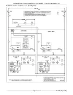
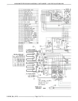
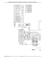
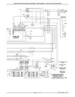
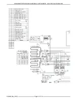
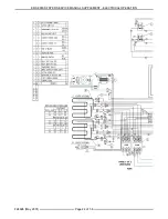
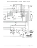
Page 9: ...ss enter to begin the test The control will respond by displaying the name of the key pressed Press exit once to return to the test menu or twice to return to normal operation With VER xxx displayed the release number is displayed as VER XXX ELECTRICAL OPERATION SEQUENCE OF OPERATION Solid State Fryer Control Full Vat Refer to schematic diagram TSP1567C for both the Fryer Controls operation and th...

Page 10: ... 4CON are de energized and power is removed from the heating elements 2 Heat light goes OFF 4 Temperature control cycles output to terminal 7 until power switch is turned OFF heating elements are raised or a high limit condition occurs A If oil reaches 410 F 5 the temperature control de energizes high limit relay on board contacts revert back to the normally CLOSED position and the output changes ...

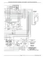
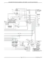
Page 11: ...odels A separate 120VAC connection is used along with step down transformer s to provide power for the fryer controls basket lift s if installed and the Kleenscreen filtering controls 4 All models require a separate 120VAC connection for the pump motor B 24VAC transformer 2T energized 1 Power to pins 3 4 5 6 11 and 17 control system main input on computer main harness 2 24 VAC ground to pins 9 12 ...

Page 12: ... control relay R1 and contactors 1 thru 4 are de energized 1 Power is removed form the heating elements and heating stops 2 R1 contacts OPEN and remove power from pin 1 full vat or right side split vat The display will indicate OFF NOTE If the second high limit trips for the left side split vat only R3 and contactors 3 and 4 are de energized Power is removed form the left side vat heating elements...

Page 13: ...d oil is returned to the vat and filter power switch is OFF open the filter drawer approximately one inch Allow the remaining shortening in the line to drain into the filter tank to prevent possible clogging after the shortening cools and solidifies Close the filter drawer when complete Discard of used oil 1 Conditions A Same as outlined in steps 1 thru 4 under KLEENSCREEN FILTERING SYSTEM 2 Open ...

Page 14: ...scard Valve Switch Energizes the filter relay coil to supply power to the pump motor through filter relay contacts N O when switch is CLOSED valve handle extended This allows the oil to be discarded through the discard hose into a separate container When filter tank is empty retract the handle to return the discard switch to normal operating position Fryer Power Switch Energizes relay coil R1 and ...

Page 15: ...ER SERIES FRYER SERVICE MANUAL SUPPLEMENT ELECTRICAL OPERATION F24696 May 2001 Page 15 of 56 COMPONENT LOCATION ...

Page 16: ...ER SERIES FRYER SERVICE MANUAL SUPPLEMENT ELECTRICAL OPERATION F24696 May 2001 Page 16 of 56 SCHEMATIC DIAGRAMS Solid State Control and Kleenscreen Filter Full Vat ...

Page 17: ...ER SERIES FRYER SERVICE MANUAL SUPPLEMENT ELECTRICAL OPERATION F24696 May 2001 Page 17 of 56 Solid State Control and Kleenscreen Filter Split Vat ...

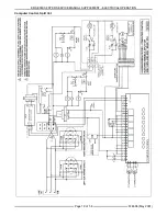
Page 18: ...ER SERIES FRYER SERVICE MANUAL SUPPLEMENT ELECTRICAL OPERATION F24696 May 2001 Page 18 of 56 Computer Control Full Vat ...

Page 19: ...ER SERIES FRYER SERVICE MANUAL SUPPLEMENT ELECTRICAL OPERATION F24696 May 2001 Page 19 of 56 Computer Control Split Vat ...

Page 20: ...ER SERIES FRYER SERVICE MANUAL SUPPLEMENT ELECTRICAL OPERATION F24696 May 2001 Page 20 of 56 Kleenscreen Filtering System Computer Control ...

Page 21: ...ER SERIES FRYER SERVICE MANUAL SUPPLEMENT ELECTRICAL OPERATION F24696 May 2001 Page 21 of 56 Heater Circuit Solid State Controls Full Vat ...

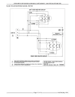
Page 22: ...ER SERIES FRYER SERVICE MANUAL SUPPLEMENT ELECTRICAL OPERATION F24696 May 2001 Page 22 of 56 Heater Circuit Solid State Controls Split Vat ...

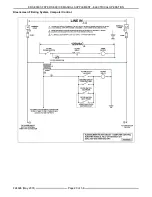
Page 23: ...ER SERIES FRYER SERVICE MANUAL SUPPLEMENT ELECTRICAL OPERATION F24696 May 2001 Page 23 of 56 Basket Lift Circuit Solid State Controls ...

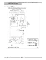
Page 24: ...ER SERIES FRYER SERVICE MANUAL SUPPLEMENT ELECTRICAL OPERATION F24696 May 2001 Page 24 of 56 WIRING DIAGRAMS Kleenscreen Filtering System ...

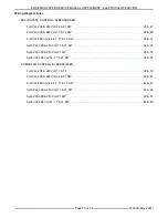
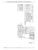
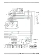
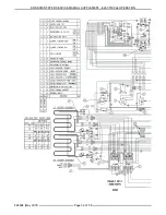
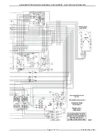
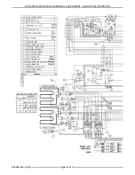
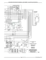
Page 25: ...14 KW 28 29 Full Vat 480 Volt 24 21 17 14 KW 30 31 Split Vat 208 240 Volt 17 14 KW 32 33 Split Vat 208 240 Volt 21 KW 34 35 Split Vat 480 Volt 14 17 21 KW 36 37 COMPUTER CONTROL KLEENSCREEN Full Vat 208 240 Volt 17 14 38 39 Full Vat 208 240 Volt 24 21 KW 40 41 Full Vat 480 Volt 24 21 17 14 KW 42 43 Split Vat 208 240 Volt 17 14 KW 44 45 Split Vat 208 240 Volt 21 KW 46 47 Split Vat 480 Volt 21 17 14...

Page 26: ...ER SERIES FRYER SERVICE MANUAL SUPPLEMENT ELECTRICAL OPERATION F24696 May 2001 Page 26 of 56 ...

Page 27: ...ER SERIES FRYER SERVICE MANUAL SUPPLEMENT ELECTRICAL OPERATION F24696 May 2001 Page 27 of 56 ...

Page 28: ...ER SERIES FRYER SERVICE MANUAL SUPPLEMENT ELECTRICAL OPERATION F24696 May 2001 Page 28 of 56 ...

Page 29: ...ER SERIES FRYER SERVICE MANUAL SUPPLEMENT ELECTRICAL OPERATION F24696 May 2001 Page 29 of 56 ...

Page 30: ...ER SERIES FRYER SERVICE MANUAL SUPPLEMENT ELECTRICAL OPERATION F24696 May 2001 Page 30 of 56 ...

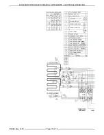
Page 31: ...ER SERIES FRYER SERVICE MANUAL SUPPLEMENT ELECTRICAL OPERATION F24696 May 2001 Page 31 of 56 ...

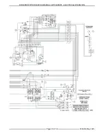
Page 32: ...ER SERIES FRYER SERVICE MANUAL SUPPLEMENT ELECTRICAL OPERATION F24696 May 2001 Page 32 of 56 ...

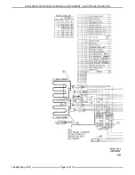
Page 33: ...ER SERIES FRYER SERVICE MANUAL SUPPLEMENT ELECTRICAL OPERATION F24696 May 2001 Page 33 of 56 ...

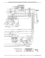
Page 34: ...ER SERIES FRYER SERVICE MANUAL SUPPLEMENT ELECTRICAL OPERATION F24696 May 2001 Page 34 of 56 ...

Page 35: ...ER SERIES FRYER SERVICE MANUAL SUPPLEMENT ELECTRICAL OPERATION F24696 May 2001 Page 35 of 56 ...

Page 36: ...ER SERIES FRYER SERVICE MANUAL SUPPLEMENT ELECTRICAL OPERATION F24696 May 2001 Page 36 of 56 ...

Page 37: ...ER SERIES FRYER SERVICE MANUAL SUPPLEMENT ELECTRICAL OPERATION F24696 May 2001 Page 37 of 56 ...

Page 38: ...ER SERIES FRYER SERVICE MANUAL SUPPLEMENT ELECTRICAL OPERATION F24696 May 2001 Page 38 of 56 ...

Page 39: ...ER SERIES FRYER SERVICE MANUAL SUPPLEMENT ELECTRICAL OPERATION F24696 May 2001 Page 39 of 56 ...

Page 40: ...ER SERIES FRYER SERVICE MANUAL SUPPLEMENT ELECTRICAL OPERATION F24696 May 2001 Page 40 of 56 ...

Page 41: ...ER SERIES FRYER SERVICE MANUAL SUPPLEMENT ELECTRICAL OPERATION F24696 May 2001 Page 41 of 56 ...

Page 42: ...ER SERIES FRYER SERVICE MANUAL SUPPLEMENT ELECTRICAL OPERATION F24696 May 2001 Page 42 of 56 ...

Page 43: ...ER SERIES FRYER SERVICE MANUAL SUPPLEMENT ELECTRICAL OPERATION F24696 May 2001 Page 43 of 56 ...

Page 44: ...ER SERIES FRYER SERVICE MANUAL SUPPLEMENT ELECTRICAL OPERATION F24696 May 2001 Page 44 of 56 ...

Page 45: ...ER SERIES FRYER SERVICE MANUAL SUPPLEMENT ELECTRICAL OPERATION F24696 May 2001 Page 45 of 56 ...

Page 46: ...ER SERIES FRYER SERVICE MANUAL SUPPLEMENT ELECTRICAL OPERATION F24696 May 2001 Page 46 of 56 ...

Page 47: ...ER SERIES FRYER SERVICE MANUAL SUPPLEMENT ELECTRICAL OPERATION F24696 May 2001 Page 47 of 56 ...

Page 48: ...ER SERIES FRYER SERVICE MANUAL SUPPLEMENT ELECTRICAL OPERATION F24696 May 2001 Page 48 of 56 ...

Page 49: ...ER SERIES FRYER SERVICE MANUAL SUPPLEMENT ELECTRICAL OPERATION F24696 May 2001 Page 49 of 56 ...

Page 50: ...light ON trouble light and first and second high limit lights ON 1 Low oil 2 First high limit inoperative control board 3 Second high limit OPEN or tilt switch OPEN or tilt switch malfunction 4 Contactor s malfunction 5 Control board malfunction Excessive time to melt shortening more than 45 minutes 1 Melt cycle timing incorrect control board 2 Heating elements malfunctioning 3 Supply power incorr...

Page 51: ...ght heat output full vat or right side split vat or pin 16 left heat output on left side split vat only 11 Computer main harness wiring problem 12 Malfunctioning computer control Fryer displays HI TEMP alarm message 1 Low oil 2 Frying oil temperature above 410 F heating elements not turning OFF A Malfunctioning heat control relay R2 full vat or right side split vat or R4 on left side split vat onl...

Page 52: ... 18 no connection 7 no connection 19 Left basket output 8 no connection 20 no connection 9 2 ground 21 no connection 10 Drain valve switch es if installed input status 22 no connection 11 1 3 Door switch input status 23 Computer power input 12 VDC nominal 12 1 2 Full vat or Split vat mode Input 24 Computer power input 12 VDC NOTES 1 24VAC control system main input to pin 17 jumpered to pins 3 4 5 ...

Page 53: ...er valve mechanical malfunction 6 Pump is inoperative Oil not discarding pump motor ON 1 Filter screen plugged 2 Clog in filter system lines NOTE If using solid shortening when all filtered oil is returned to the vat and filter power switch is OFF open the filter drawer approximately one inch Allow the remaining shortening in the line to drain into the filter tank to prevent possible clogging afte...

Page 54: ...ER SERIES FRYER SERVICE MANUAL SUPPLEMENT F24696 May 2001 Page 54 of 56 NOTES ...

Page 55: ...ER SERIES FRYER SERVICE MANUAL SUPPLEMENT F24696 May 2001 Page 55 of 56 NOTES ...

Page 56: ... 1 Temperature Probe Thermistor X 1 417876 1 Resistor Heat Light X 1 415144 12 Temperature Control Board X 1 415638 G1 Potentiometer Assy X 1 411496 B1 Rocker Switch Fry Melt X 1 411497 C3 Contactor 3 Pole 40 Amp 120v Coil X 1 X 2 411497 C5 Contactor 3 Pole 40 Amp 240v Coil X 1 X 2 418159 1 Cam Switch Basket Lift X 1 X 2 418156 1 Gear Motor Basket Lift X 1 X 2 416741 G5 Element 208v 14kw X 1 X 2 4...

Reviews: