REMOVAL AND REPLACEMENT OF PARTS
CONTROL PANEL
Disconnect the
electrical power to the machine and
follow lockout / tagout procedures.
The Control Panel holds the thermostats, indicator
lights and power switch.
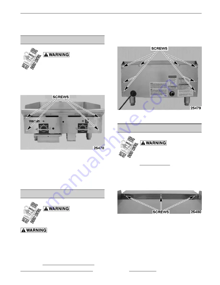
1. Remove four screws securing the front of control
panel to frame.
Fig. 1
2. Remove screw(s) that secure the bottom lip of
the control panel to the frame. The total number
of screws depend on the width of the griddle.
3. Pull control panel forward and lay face down in
front of the unit while servicing.
4. Reverse procedure to install.
BACK PANEL
Disconnect the
electrical power to the machine and
follow lockout / tagout procedures.
Shut off the gas before servicing the
unit.
NOTE:
Remove the back panel when changing a
burner, temperature probe or to remove excessive
grease build up from the flue area.
1. Disconnect gas supply at griddle.
2. Remove GAS PRESSURE REGULATOR.
3. Remove all screws from rear of griddle securing
the back panel.
Fig. 2
4. Reverse procedure to install.
BULL NOSE
Disconnect the
electrical power to the machine and
follow lockout / tagout procedures.
1. Remove CONTROL PANEL.
2. Remove all screws securing bull nose to griddle.
The total number of screws depend on the width
of the griddle.
Fig. 3
3. Lift bull nose off griddle.
4. Reverse procedure to install.
RRG SERIES HEAVY DUTY GAS GRIDDLE - REMOVAL AND REPLACEMENT OF PARTS
Page 5 of 24
F45514 (0214)


