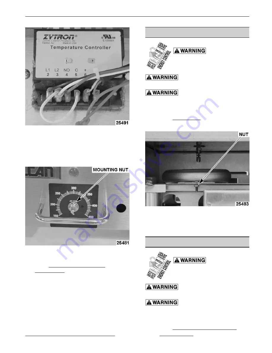
Fig. 6
3. Remove knob from temperature control shaft.
4. Note temperature control orientation as mounted
to control panel. Remove mounting nut from
temperature control shaft and remove control
from panel.
Fig. 7
5. Reverse procedure to install.
6. Check TEMPERATURE CONTROL
CALIBRATION.
BURNER
Disconnect the
electrical power to the machine and
follow lockout / tagout procedures.
Shut off the gas before servicing the
unit.
All gas joints disturbed during
servicing must be checked for leaks. Check with a
soap and water solution (bubbles). Do not use an open
flame.
1. Remove BACK PANEL.
2. Remove the nut that is securing burner.
Fig. 8
3. Lift back of burner until locating pin clears hole
and pull out burner.
4. Reverse proceedure to install.
PILOT BURNER
Disconnect the
electrical power to the machine and
follow lockout / tagout procedures.
Shut off the gas before servicing the
unit.
All gas joints disturbed during
servicing must be checked for leaks. Check with a
soap and water solution (bubbles). Do not use an open
flame.
1. Remove GAS PRESSURE REGULATOR.
RRG SERIES HEAVY DUTY GAS GRIDDLE - REMOVAL AND REPLACEMENT OF PARTS
Page 7 of 24
F45514 (0214)


