BURNER
Disconnect the electrical power to
the machine and follow lockout /
tagout procedures.
Shut off the gas before servicing the
unit and follow lockout / tagout
procedures.
All gas joints disturbed during servicing must be
checked for leaks. Check with a soap and water
solution (bubbles). Do not use an open flame.
1.
Remove FRONT PANEL and BACK PANEL.
2.
Disconnect gas supply at griddle.
3.
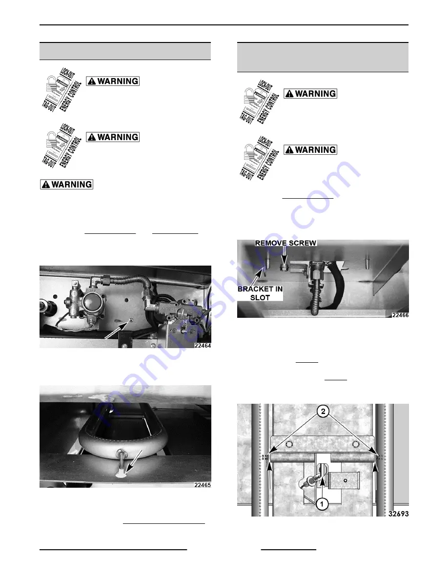
Remove screw securing burner to wall.
Fig. 13
4.
At rear of unit, pull burner enough to disengage
burner pin from frame and pull burner out.
Fig. 14
5.
Install in reverse order.
6.
Adjust as outlined in BURNER ADJUSTMENT.
PILOT, THERMOCOUPLE
ASSEMBLY
Disconnect the electrical power to
the machine and follow lockout /
tagout procedures.
Shut off the gas before servicing the
unit and follow lockout / tagout
procedures.
1.
2.
From underneath the front of the griddle, remove
screw securing pilot assembly bracket.
VIEW FROM REAR OF UNIT TO SEE PARTS
Fig. 15
3.
Carefully lift to disengage bracket from slot and
work assembly down to access parts.
4.
With pilot (1, Fig. 16) centered in flash tube
opening, center align ignition ports with both
sides of flash tube (2, Fig. 16). Verify 1/8” gap
between the end of flash tube and burner on both
sides.
Fig. 16
Heavy Duty Gas Griddles - REMOVAL AND REPLACEMENT OF PARTS
Page 9 of 19
F25383 (0219)


