6.
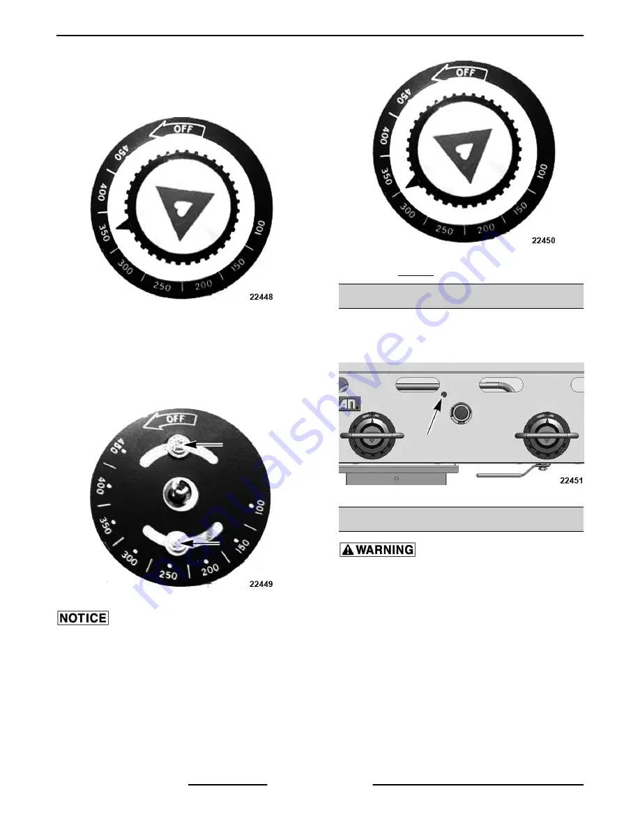
Carefully loosen the knob set screw. DO NOT
allow the knob to turn. Carefully remove the knob
from the thermostat shaft, exposing the
temperature dial.
Fig. 21
7.
Loosen screws on the temperature dial and
adjust it so that the temperature indicated by the
knob arrow matches the griddle plate
temperature reading. Knob will have to be
carefully placed back on the shaft to verify
adjustment.
Fig. 22
Never adjust the screw in the center of the thermostat
shaft. This will ruin the factory calibration; the
thermostat will no longer operate properly and will
need to be replaced.
8.
Once calibration is achieved, tighten the
temperature dial screws and knob set screws.
Fig. 23
9.
Repeat Steps 3 thru 8 for each zone.
PILOT ADJUSTMENT
Using a flathead screwdriver, turn the slotted pilot
adjustment screw clockwise to decrease the flame,
and counterclockwise to increase the flame.
Fig. 24
GAS PRESSURE MEASUREMENT
All gas joints disturbed during servicing must be
checked for leaks. Check with a soap and water
solution (bubbles). Do not use an open flame.
1.
Turn the gas supply off at a manual shutoff valve.
2.
Remove the control panel.
3.
Remove the pressure tap plug and attach
manometer.
4.
Turn gas back on.
5.
Light pilot(s).
6.
Turn all thermostats on to the maximum setting
so that all burners are on.
7.
Turn all the equipment on the same supply line
on.
Heavy Duty Gas Griddles - SERVICE PROCEDURES AND ADJUSTMENTS
F25383 (0219)
Page 12 of 19


