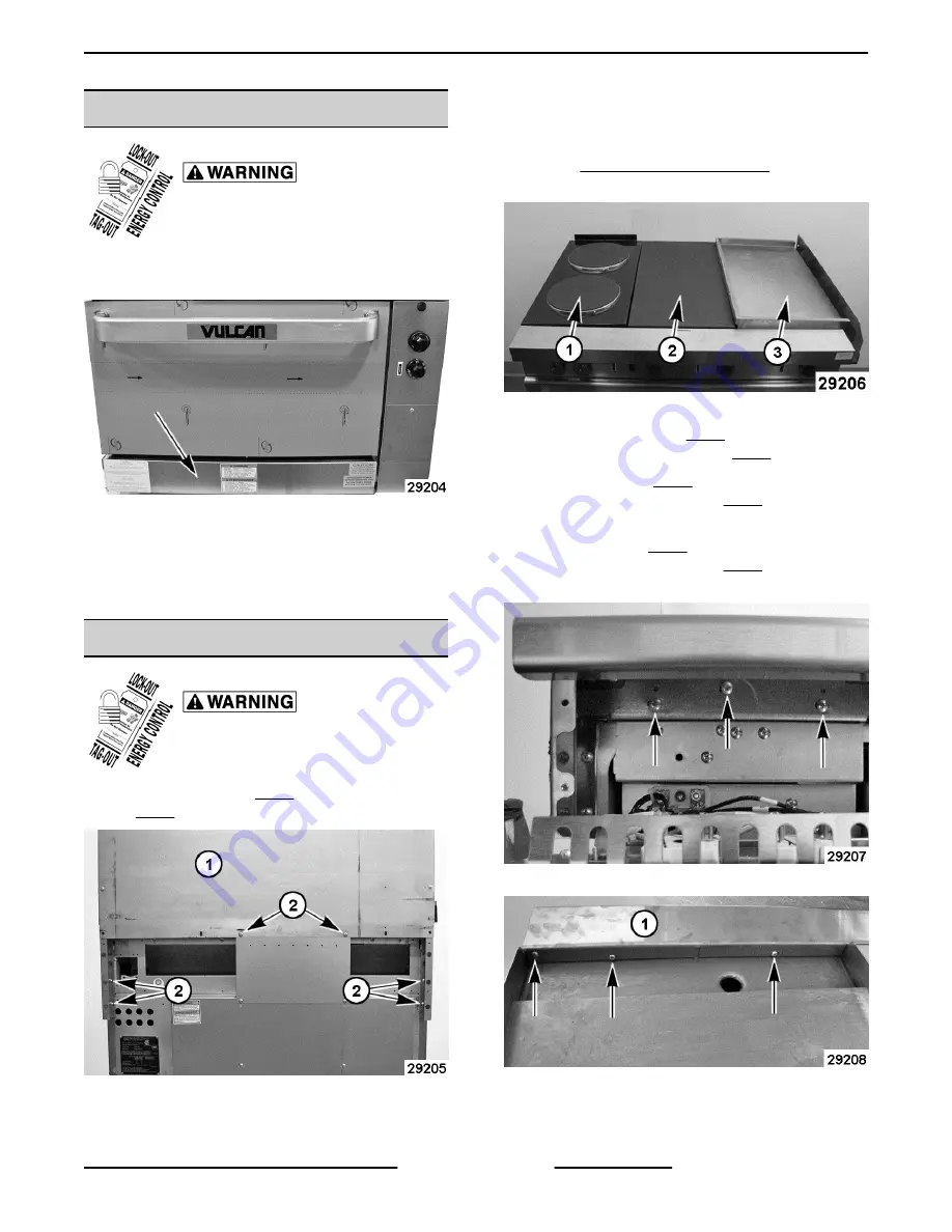
KICK PANEL
Disconnect the
electrical power to the machine and
follow lockout / tagout procedures.
1.
Lift kick panel to disengage from the mounting
bracket upper pin and allow panel to rotate down.
Fig. 4
2.
Apply outward pressure on one of the panel
mounting ends to disengage from mounting
bracket lower pin.
3.
Reverse procedure to install.
RANGE TOPS
Disconnect the
electrical power to the machine and
follow lockout / tagout procedures.
1.
Remove screws (2, Fig. 5) securing backsplash
(1,Fig. 5) to frame.
Fig. 5
2.
Lift backsplash to disengage the support tabs
from mounting slots in frame. Place backsplash
to the side until ready to install.
3.
4.
Remove range top as described below:
Fig. 6
A.
French Plate (1, Fig. 6) - Remove screws
securing French Plate (Fig. 7) to frame.
B.
Hot Top (2, Fig. 6) - Remove screws
securing bull nose (1, Fig. 8) to frame then
lift bull nose off range.
C.
Griddle (3, Fig. 6) - Remove screws
securing bull nose (1, Fig. 8) to frame then
lift bull nose off range.
Fig. 7
Fig. 8
EV Series Electric Ranges - REMOVAL AND REPLACEMENT OF PARTS
Page 7 of 33
F45586 (0716)
Summary of Contents for EV12 Series
Page 24: ...EV12 RANGE TOP 480V EV Series Electric Ranges WIRING DIAGRAMS F45586 0716 Page 24 of 33 ...
Page 25: ...EV24 RANGE TOPS 208V 240V EV Series Electric Ranges WIRING DIAGRAMS Page 25 of 33 F45586 0716 ...
Page 29: ...EV24 RANGE TOPS 480V EV Series Electric Ranges WIRING DIAGRAMS Page 29 of 33 F45586 0716 ...
Page 30: ...EV24 STANDARD OVEN 480V EV Series Electric Ranges WIRING DIAGRAMS F45586 0716 Page 30 of 33 ...
Page 31: ...EV36 RANGE TOPS 480V EV Series Electric Ranges WIRING DIAGRAMS Page 31 of 33 F45586 0716 ...
Page 32: ...EV36 STANDARD OVEN 480V EV Series Electric Ranges WIRING DIAGRAMS F45586 0716 Page 32 of 33 ...


