background image

FILLING THE RESERVOIR JACKET

NOTE: 

 The reservoir water level must be maintained

high enough to keep contact with the water level probe
(LLCO). If low water light comes on during use, the
visible level may be below the water level probe and
must be replenished before heating can continue. The
low water light will come on when kettle is tilted (tilting
models only).

When filling reservoir jacket, use only distilled water
and heat transfer fluid. The ratio is 67% distilled water
and the 33% heat transfer fluid.

NOTE: 

 Jacket fill port plumbing: A pipe elbow and

pipe plug are installed on current construction kettles
to open the fill port. A manual valve with knob was
installed on previous construction kettles to open the
fill port.

Partial Refill

1.

Place kettle in full upright position (tilting models
only).

2.

Turn power switch on.

A.

If water level in sight glass is 1/3 full then
water level is ok.

B.

If low water light is on, check to see if water
level in sight glass is below 1/4 full. If water
level is low, continue with procedure to refill.

3.

Set temperature dial to lowest setting.

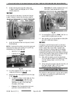
Pressure Relief Valve Exhaust. DO NOT connect
to building water, gas, or steam supply. DO NOT
block or restrict.

Hot steam. The kettle and its parts are hot. Use
care when operating, cleaning or servicing the
kettle.

4.

Open pressure relief valve until reservoir jacket
is completely vented. Allow valve to snap shut to
seal.

5.

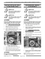
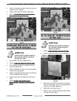
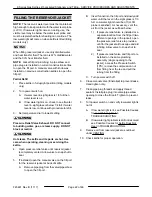
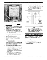
If installed, open the manual valve on the fill port
for the reservoir jacket at back of kettle.

A.

Remove pipe plug from the valve/pipe elbow
to open the fill port.

B.

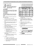
Insert funnel into the fill port and slowly add
water until the level in the sight glass is 1/3
full. Low water light should be off (LLCO
probe is satisfied). As necessary, vent the
air from the jacket as outlined below:

1)

If pressure relief valve is installed at a
separate location from the fill port (two
different openings in the jacket), open
the pressure relief valve to provide a
vent for the jacket air to escape and aid
in filling. Allow valve to snap shut to
seal.

2)

If pressure relief valve and fill port are
installed on the same plumbing
assembly (single opening to the
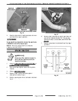
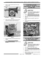
jacket), access the Pressure Switch
(1PS), remove the compression nut
from fitting near the tee and pull the
tubing from the fitting.

C.

Turn power switch off.

6.

Close manual valve (if installed) to prevent leaks.
Hand tighten only.

7.

Clean pipe plug threads and apply thread
sealant. Install pipe plug into valve/pipe elbow
opening to close the fill port. Tighten to prevent
leaks.

8.

Turn power switch on and verify low water light is
not lit.

A.

If low water light is lit, see Possible Causes
for Low Water Light Lit in
TROUBLESHOOTING.

B.

If low water light problem is still not resolved
see Possible Causes for Kettle Does Not
Heat in TROUBLESHOOTING.

9.

Remove air from reservoir jacket as outlined
under VENTING.

10. Check kettle for proper operation.

K Series Gas Kettles 2/3 Jacketed Stationary and Tilting - SERVICE PROCEDURES AND ADJUSTMENTS

F45461 Rev. B (1117)

Page 22 of 48

Summary of Contents for K20GL

Page 1: ...you have the necessary tools instruments and skills required to perform the procedure Procedures for which you do not have the necessary tools instruments and skills should be performed by a trained Vulcan Service Technician The reproduction transfer sale or other use of this Manual without the express written consent of Vulcan is prohibited This manual has been provided to you by ITW Food Equipme...

Page 2: ...G OPTION ONLY 17 SERVICE PROCEDURES AND ADJUSTMENTS 19 TEMPERATURE CONTROLLER TEST 19 POTENTIOMETER TEST 20 THERMOCOUPLE TEST 20 VENTING 20 FILLING THE RESERVOIR JACKET 22 PARTIAL REFILL 22 COMPLETE DRAINING AND REFILL 23 BLOWER INLET PRESSURE CHECK 24 GAS VALVE BLOWER INLET PRESSURE CHECK 108W 24 TO ADJUST 25 GAS VALVE BLOWER INLET PRESSURE CHECK 130W 25 SPARK IGNITION TEST 26 FLAME SENSE CURRENT...

Page 3: ...TING OPTION 40 SCHEMATIC DIAGRAM STATIONARY TILTING MODELS 42 SCHEMATIC DIAGRAM POWER TILTING OPTION 44 TROUBLESHOOTING 45 STATIONARY TILTING GENERAL 45 POWER TILTING OPTION ONLY 47 K Series Gas Kettles 2 3 Jacketed Stationary and Tilting VULCAN 2017 Page 3 of 48 F45461 Rev B 1117 ...

Page 4: ...ated FILLING THE RESERVOIR JACKET Updated GAS VALVE BLOWER INLET PRESSURE CHECK 108W Added GAS VALVE BLOWER INLET PRESSURE CHECK 130W Update TOOLS K Series Gas Kettles 2 3 Jacketed Stationary and Tilting SERVICE UPDATES F45461 Rev B 1117 Page 4 of 48 ...

Page 5: ...ually using the crank handle as needed K Series Floor Model Kettles The 2 3 jacketed gas kettles are self contained The lower two thirds of the kettle bowl is a double wall stainless steel construction that provides a reservoir for a solution of heat transfer fluid and distilled water for improved heating of the kettle contents The kettles are used to prepare a variety of liquid or semi liquid foo...

Page 6: ...ectronic ignition systems should be connected to a standard 120VAC electrical outlet rather than a ground fault circuit interrupter GFCI if possible Machines connected to certain GFCI circuits may repeatedly nuisance trip the GFCI If the machine must be connected to a GFCI use Part No 913053 Pass and Seymour approved by engineering for use with electronic ignition systems Gas Supply NOTICE The gas...

Page 7: ...s later total time delay of 15 sec to high speed and runs until set point temperature is satisfied Cycle repeats upon call for heat Kettle Rating All models listed on front cover have an input BTU rating of 100 000 BTU HR OPERATION CLEANING AND MAINTAINENCE Refer to F35461 Installation Operation Manual for specific instructions The manual includes A page from the Stainless Steel Care and Cleaning ...

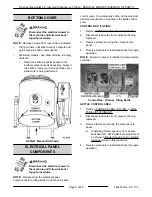
Page 8: ...held in place using the same number of screws K20GLT Manual Tilt Shown CORNER REAR PANELS TILTING Disconnect the electrical power to the machine and follow lockout tagout procedures NOTE Remove screws from panel where indicated K20GLT Manual Tilt Shown SIDE REAR PANELS STATIONARY Disconnect the electrical power to the machine and follow lockout tagout procedures NOTE Remove screws from panel where...

Page 9: ...e electrical panel components are mounted in the kettle control area CONTROL BOX TILTING 1 Remove CONTROL BOX COVER TILTING 2 Disconnect lead wires from component being replaced 3 Remove screws securing the component to panel 4 Reverse procedure to install and check for proper operation NOTE Ensure J1 jumper is installed on temperature controller Control Box K Series Tilting Kettle KETTLE CONTROL ...

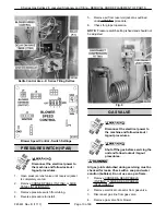
Page 10: ...NOTE Pressure switch setting is fixed and should not be adjusted Fig 9 GAS VALVE Disconnect the electrical power to the machine and follow lockout tagout procedures Shut off the gas before servicing the unit and follow lockout tagout procedures All gas joints disturbed during servicing must be checked for leaks Check with a soap and water solution bubbles Do not use an open flame 1 Remove CORNER R...

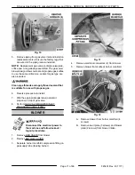
Page 11: ... the appropriate gas label natural or propane on top of gas valve 8 Perform GAS VALVE BLOWER INLET PRESSURE CHECK 108W BLOWER Disconnect the electrical power to the machine and follow lockout tagout procedures 1 Remove GAS VALVE from blower 2 Remove BOTTOM COVER 3 Separate burner manifold compression fitting on gas supply tube feeding burner Fig 11 4 Remove electrical connectors 2 from blower 5 Re...

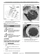
Page 12: ...n open flame 1 Remove BOTTOM COVER 2 Remove clips securing insulation to bottom of kettle A Gently remove insulation and save for reuse 3 Disconnect spark ignitor lead wires at the ignition module 4 Separate compression nuts on gas supply tube 5 Loosen gas manifold mounting nuts and remove gas supply tube from the fittings Fig 14 6 Remove combustion chamber cover from bottom of kettle Fig 15 7 Not...

Page 13: ...NG or CORNER PANEL STATIONARY 2 Disconnect spark ignitor lead wires at ignition module 3 Remove BOTTOM COVER 4 Remove clips holding insulation against combustion chamber cover 5 Remove spark ignitor from combustion chamber cover Fig 17 6 Ensure spark gap between ignitor electrode and ground rod is approximately 1 8 If necessary adjust as outline under SPARK IGNITION TEST Step 8C 7 Reverse procedur...

Page 14: ...se with propane gases GEAR REDUCER MANUAL TILTING MODELS Disconnect the electrical power to the machine and follow lockout tagout procedures Shut off the gas before servicing the unit and follow lockout tagout procedures All gas joints disturbed during servicing must be checked for leaks Check with a soap and water solution bubbles Do not use an open flame 1 Place kettle in the fully upright posit...

Page 15: ...TROL BOX COVER TILTING 2 Disconnect lead wires from component being replaced 3 Remove screws securing the component to panel 4 Reverse procedure to install and check for proper operation Fig 23 TILT SWITCH 2S POWER TILTING OPTION ONLY Disconnect the electrical power to the machine and follow lockout tagout procedures 1 Place kettle in the fully upright position 2 Remove CONTROL BOX COVER TILTING 3...

Page 16: ...nting nuts and screws 2 securring down limit switch 3S to bracket 6 Reverse procedure to install down limit switch 3S 7 Perform DOWN LIMIT SWITCH 3S ADJUSTMENT POWER TILTING OPTION ONLY Fig 25 DC TILT MOTOR POWER TILTING OPTION ONLY Disconnect the electrical power to the machine and follow lockout tagout procedures 1 Remove CONTROL BOX COVER TILTING 2 Remove motor cover from rear of control box Fi...

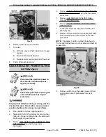
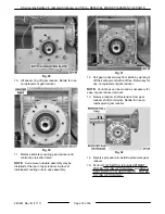
Page 17: ...Raise it slightly to take the kettle pivot shaft weight off gear reducer 3 Remove TILT SWITCH 2S POWER TILTING OPTION ONLY leaving the lead wires connected 4 Remove DOWN LIMIT SWITCH 3S POWER TILTING OPTION ONLY leaving the lead wires connected 5 Remove GAS SHUT OFF VALVE 1SOL TILTING MODELS ONLY 6 Remove DC TILT MOTOR POWER TILTING OPTION ONLY 7 Loosen set screw securing arm to kettle pivot shaft...

Page 18: ...tle pivot shaft until free Retain key for use on replacement gear reducer NOTE Control box can be moved as necessary for ease of gear reducer removal 13 Remove reducer shaft extension from gear reducer shaft 2 roll pins Retain for use on replacement gear reducer Fig 32 14 Reverse procedure to install replacement gear reducer 15 Perform TILT SWITCH 2S ADJUSTMENT POWER TILTING OPTION ONLY and DOWN L...

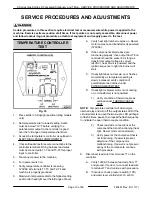
Page 19: ...ioning properly then output from T8 on controller should be present As long as transformer output voltage is correct 24VAC heat circuit is powered and the ignition sequence to light the burner will start C If heat light does not remain on or flashes momentarily as temperature setting is slowly increased verify condition of potentiometer as outlined under POTENTIOMETER TEST D If heat light or blowe...

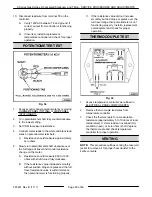
Page 20: ...lue increased smoothly without sudden drops or spikes and the full travel resistance value is within tolerance then potentiometer is functioning properly C If the resistance value did not increase smoothly but had drops or spikes over the full travel range then potentiometer is not functioning properly Install a replacement potentiometer and check for proper operation THERMOCOUPLE TEST Fig 35 1 Ac...

Page 21: ... NOT block or restrict Hot steam The kettle and its parts are hot Use care when operating cleaning or servicing the kettle 6 Open pressure relief valve for approximately 10 seconds Allow valve to snap shut to seal Current Construction Previous Construction 7 Turn power switch off and allow kettle to cool room temperature Verify pressure gauge reading is within the correct vacuum range A If reading...

Page 22: ... installed open the manual valve on the fill port for the reservoir jacket at back of kettle A Remove pipe plug from the valve pipe elbow to open the fill port B Insert funnel into the fill port and slowly add water until the level in the sight glass is 1 3 full Low water light should be off LLCO probe is satisfied As necessary vent the air from the jacket as outlined below 1 If pressure relief va...

Page 23: ...pen the manual valve on the fill port for the reservoir jacket at back of kettle C Remove pipe plug from valve pipe elbow to open the fill port D Insert funnel into the fill port and slowly add mixture of water and heat transfer fluid to the reservoir jacket Fill the jacket according to the volumes listed in the table below The level in the sight glass should be 1 3 full RESERVOIR JACKET VOLUME Mo...

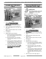
Page 24: ...K 108W GAS VALVE BLOWER INLET PRESSURE CHECK 108W Shut off the gas before servicing the unit and follow lockout tagout procedures NOTE Wattage is listed on blower label Fig 40 1 Remove CORNER REAR PANELS TILTING or SIDE REAR PANELS STATIONARY to access blower gas valve 2 Open inlet pressure port Turn screw 1 to 2 turns CCW 3 Attach slack tube manometer hose to inlet pressure port 4 Attach U inclin...

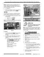
Page 25: ... screw fully clockwise until it stops Natural Turn screw 15 turns counterclockwise Propane Turn screw 9 turns counterclockwise Fig 42 GAS VALVE BLOWER INLET PRESSURE CHECK 130W Shut off the gas before servicing the unit and follow lockout tagout procedures NOTE This check is for K series gas kettle models K20GL K20GLT K40GL K40GLT K60GL K60GLT with serial number 463023802 to present and built on 5...

Page 26: ...urns Fig 45 12 Turn temperature control to BOIL and turn on power switch to initiate ignition series 13 After a warmup of 10 minutes begin sampling flue gas with a calibrated analyzer Flue gasses must be checked with a combustion analyzer Combustion limits are listed below If the burner system fails to meet these requirements please call Steam Technical Support immediately Insert sampling probe in...

Page 27: ...hich can permit leakage to ground If either of these conditions exists then install a replacement spark ignitor B Inspect the spark ignitor electrode and ground rod for contaminates or corrosion Clean those surfaces as necessary C Spark gap between the spark ignitor electrode and ground rod should be approximately 1 8 If the gap is outside of this dimension bend the spark ignitor electrode as nece...

Page 28: ...nd set the temperature dial to call for heat A Power 1LT light and heat light 3LT come ON 3 Ignition control module is energized and trial for ignition starts 6 seconds A Verify 24VAC between terminals 25V 25V GND If voltage is not present check transformer 1T output voltage 4 Spark voltage is sent from spark terminal to the spark ignitor electrode and sparking begins At the same time the ignition...

Page 29: ...y upright the top of kettle should be horizontal when viewed from either side 2 Turn crank handle clockwise to tilt the kettle until it stops Kettle should be tilted past 90 to allow contents to drain 3 If adjustment is necessary continue with procedure 4 Remove CONTROL BOX COVER TILTING 5 Return kettle to fully upright position A The inner jam nut should be in solid contact with positive stop tra...

Page 30: ... Tilt Switch 2S 2 Kettle tilt operation The switch actuator should be operated by the arm when the kettle is fully upright to open the N C contacts and stop travel 3 If adjustment is necessary loosen the tilt switch mounting bracket screws 2 and position the switch to obtain the proper tilt switch operation The mounting bracket holes are slotted to allow for adjustment A Kettle fully upright Tilt ...

Page 31: ... 55 1 Access the DC tilt motor controller as outlined under ELECTRICAL PANEL COMPONENTS POWER TILTING OPTION ONLY Set VOM to measure AC volts and connect meter leads at L1 L2 on the controller 2 Turn power switch on 3 Verify 120VAC at L1 L2 on the controller when the tilt motor switch momentary is operated to lower and raise the kettle A If voltage is present but kettle does not raise lower procee...

Page 32: ...voltage is not present and the DC fuse is ok turn the power switch off and disconnect power to the machine 8 Install a replacement DC tilt motor controller and check for proper operation K Series Gas Kettles 2 3 Jacketed Stationary and Tilting SERVICE PROCEDURES AND ADJUSTMENTS F45461 Rev B 1117 Page 32 of 48 ...

Page 33: ... use This increases seal life on the special fittings Timer 1TMR Delay on Make Provides a 15 second delay before energizing relay K4 Relay K4 Relay contacts provide 24VAC input signal to blower speed control connector pins J5 4 or J5 3 for blower motor low and high speed operation Relay Raise Enable K3 Power tilting option only Allows kettle to raise when the tilt switch 2S is un operated kettle t...

Page 34: ...on as viewed from shaft end Transformer 2T Steps down supply voltage to 24VAC power tilt circuit voltage Tilt Motor Switch Momentary On Off On Energizes K1 relay coil thru K3 raise enable contacts N O to raise the kettle Energizes K2 relay coil thru down limit switch contacts N C to tilt the kettle The switch positions are Center neutral starting position off Momentary on tilt kettle Momentary on ...

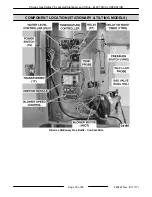
Page 35: ...COMPONENT LOCATION STATIONARY TILTING MODELS K Series Stationary Gas Kettle Controls Side K Series Gas Kettles 2 3 Jacketed Stationary and Tilting ELECTRICAL OPERATION Page 35 of 48 F45461 Rev B 1117 ...

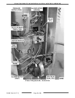
Page 36: ...K Series Tilting Gas Kettle Controls Side K Series Gas Kettles 2 3 Jacketed Stationary and Tilting ELECTRICAL OPERATION F45461 Rev B 1117 Page 36 of 48 ...

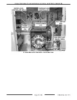
Page 37: ...K Series Manual Tilt Gas Kettle Control Box Area K Series Gas Kettles 2 3 Jacketed Stationary and Tilting ELECTRICAL OPERATION Page 37 of 48 F45461 Rev B 1117 ...

Page 38: ...Tilt refer to Sequence of Operation Power Tilt Option and schematic diagram AI3538 1 Conditions A Kettle connected to 120VAC supply and is properly grounded B Kettle connected to correct gas supply and the supply is on C Power switch 1S and light 1LT amber are off D Low water light 2LT red is off K Series Gas Kettles 2 3 Jacketed Stationary and Tilting ELECTRICAL OPERATION F45461 Rev B 1117 Page 3...

Page 39: ...ation PWM output signal to the blower motor for low or high speed operation C Blower speed control powered at connector J5 4 for blower motor low speed operation through K4 N C contacts Blower at low speed D Ignition module energized and trial for ignition begins The module generates spark at ignitor and energizes the dual gas valve coils to open the valves and provide gas for the gas air mixture ...

Page 40: ...rol circuit and heating stops 2 With 2S N C contacts closed Raise enable relay coil K3 is energized and K3 N O contacts close No power is transferred to K1 up relay until tilt motor switch is operated to raise the kettle 4 Kettle reaches full tilt position at approximately 95 and the down limit switch is operated The down limit switch N C contacts open and K2 relay coil is de energized A The three...

Page 41: ...tacts return to the open position Power is removed from the DC motor controller the DC tilt motor and kettle travel stops K Series Gas Kettles 2 3 Jacketed Stationary and Tilting ELECTRICAL OPERATION Page 41 of 48 F45461 Rev B 1117 ...

Page 42: ...SCHEMATIC DIAGRAM STATIONARY TILTING MODELS Fig 60 K Series Gas Kettles 2 3 Jacketed Stationary and Tilting ELECTRICAL OPERATION F45461 Rev B 1117 Page 42 of 48 ...

Page 43: ...Fig 61 K Series Gas Kettles 2 3 Jacketed Stationary and Tilting ELECTRICAL OPERATION Page 43 of 48 F45461 Rev B 1117 ...

Page 44: ...SCHEMATIC DIAGRAM POWER TILTING OPTION Fig 62 K Series Gas Kettles 2 3 Jacketed Stationary and Tilting ELECTRICAL OPERATION F45461 Rev B 1117 Page 44 of 48 ...

Page 45: ...ply voltage to kettle 2 Fluid level in reservoir jacket below water level probe LLCO Check fluid level in sight glass 3 Kettle jacket was refilled incorrectly with deionized or reverse osmosis RO water Use distilled water only NOTE Add approximately 1 8 teaspoon of salt to jacket fluid Lightly rinse fill port and close it 4 Water level probe LLCO wiring connection malfunction or probe coated not s...

Page 46: ...J1 or malfunction NOTE Controller LED is ON when output is closed 8 Blower does not increase to high speed A Delay on make timer 1TMR malfunction B Relay K1 malfunction N O contacts remain open with coil energized Provides high speed signal to blower speed control C Blower speed control switches not set properly or control malfunction no output voltage to blower J6 1 24VDC J6 2 COM J6 4 PWM pulse ...

Page 47: ...rrent too low dirty or corroded probe or flame sense wire connection corroded 7 Ignition module malfunction no sparking at ignitor 8 Blower speed control switches not set properly or control malfunction no output voltage to blower J6 1 24VDC J6 2 COM J6 4 PWM pulse width modulation speed signal not measurable with VOM 9 Blower intake clogged or blower malfunction 10 Gas valve not adjusted properly...

Page 48: ...ilt motor switch malfunction momentary on tilt 4 Down limit switch open or malfunction 5 K2 down relay malfunction 6 DC tilt motor controller Fuses open or controller malfunction 7 DC tilt motor inoperative 8 Gear reducer malfunction K Series Gas Kettles 2 3 Jacketed Stationary and Tilting TROUBLESHOOTING F45461 Rev B 1117 Page 48 of 48 ...

Reviews: