THERMOCOUPLE (INFRARED
BURNER)
Disconnect the
electrical power to the machine and
follow lockout / tagout procedures.
Removal
1.
2.
3.
Remove CONTROL DEFLECTOR (HEAT
SHIELD).
4.
Note thermocouple connections then disconnect
from temperature controller.
5.
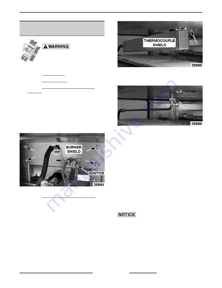
Remove burner shield to access the
thermocouple shield and thermocouple.
NOTE:
The burner shield provides a slotted opening
to support the front mounting tab on thermocouple
shield.
Fig. 19
6.
Remove IGNITOR (INFRARED BURNER) from
burner shield.
7.
Push thermocouple shield toward the front of
griddle to disengage the rear mounting tab on
thermocouple shield from the support bracket on
the bottom of griddle plate.
Fig. 20
8.
Loosen mounting nut and remove thermocouple
probe from bottom of griddle plate.
Fig. 21
9.
Remove insulating sleeve from thermocouple
wires and retain for use on replacement
thermocouple.
Installation
1.
Slide insulating sleeve over thermocouple wires.
2.
Apply a thin coating of heat transfer and anti-
seize compound to the thermocouple probe tip
and mounting nut threads.
3.
Route thermocouple probe through the front
opening in griddle frame and lay it on top of
burner.
4.
From rear of griddle, thread thermocouple probe
into the mounting hole in griddle plate and stop
when probe tip touches the plate. Torque the
mounting nut to a maximum of 25 in-lbs.
Do not over tighten or damage to the
thermocouple probe may occur. Due to the aluminum
plate core, it is also possible to create a raised area
over the probe if overtightened.
5.
Insert rear mounting tab on thermocouple shield
into the support bracket on the bottom of griddle
plate.
VCCG Series Heavy Duty Gas Griddle - REMOVAL AND REPLACEMENT OF PARTS
Page 11 of 26
F45533 (1014)


