6.
Route thermocouple wires through the opening
in burner shield. Lift burner shield and position it
so the front mounting tab on the thermocouple
shield can be inserted into the upper slotted
opening in the burner shield. Secure burner
shield to griddle.
7.
Install ignitor to burner shield.
8.
Connect thermocouple wires to the temperature
controller.
9.
Install control deflector (heat shield).
10. Install front and back panels.
11. Check TEMPERATURE CONTROLLER
IGNITOR (INFRARED BURNER)
Disconnect the
electrical power to the machine and
follow lockout / tagout procedures.
1.
2.
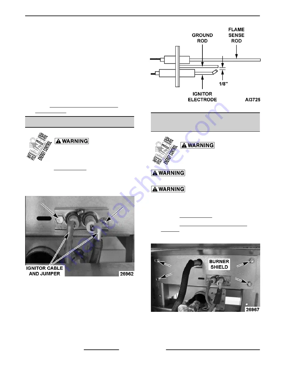
Note connection locations then disconnect ignitor
cable and jumper from ignitor terminals.
3.
Remove screws securing ignitor to burner shield.
Fig. 22
4.
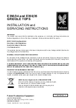
Ensure spark gap between ignitor electrode and
ground rod is approximately 1/8". If adjustment is
necessary, position the ground rod to achieve the
correct spark gap.
5.
Reverse procedure to install and check for proper
operation.
Fig. 23
PILOT ORIFICE (INFRARED
BURNER)
Disconnect the
electrical power to the machine and
follow lockout / tagout procedures.
Shut off the gas before servicing the
unit.
All gas joints disturbed during
servicing must be checked for leaks. Check with a
soap and water solution (bubbles). Do not use an open
flame.
1.
2.
Remove CONTROL DEFLECTOR (HEAT
SHIELD).
3.
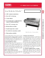
Remove burner shield.
Fig. 24
4.
Disconnect compression fitting from pilot orifice
fitting.
VCCG Series Heavy Duty Gas Griddle - REMOVAL AND REPLACEMENT OF PARTS
F45533 (1014)
Page 12 of 26


