TEMPERATURE CONTROLLER
Disconnect the
electrical power to the machine and
follow lockout / tagout procedures.
1.
2.
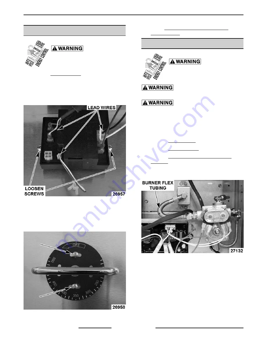
Note wire connections then disconnect them
from temperature controller.
3.
Loosen screws securing knob guard to front
panel to provide clearance for knob removal.
Fig. 4
4.
Loosen set screw then remove knob from
temperature control shaft.
5.
Remove screws securing temperature controller
to front panel.
Fig. 5
6.
Reverse procedure to install.
7.
Check TEMPERATURE CONTROLLER
CALIBRATION.
RADIANT BURNER
Disconnect the
electrical power to the machine and
follow lockout / tagout procedures.
Shut off the gas before servicing the
unit.
All gas joints disturbed during
servicing must be checked for leaks. Check with a
soap and water solution (bubbles). Do not use an open
flame.
NOTE:
Radiant burner is removed through the front
of griddle.
1.
2.
3.
Remove CONTROL DEFLECTOR (HEAT
SHIELD).
4.
Remove burner flexible tubing from the burner
orifice elbow and gas valve fitting.
Fig. 6
5.
Disconnect compression fitting from gas valve
inlet and slide gas valve off the tubing.
VCCG Series Heavy Duty Gas Griddle - REMOVAL AND REPLACEMENT OF PARTS
F45533 (1014)
Page 6 of 26


