4
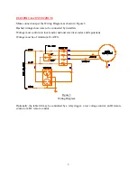
The lift motor equipped with built-in limit switches for both raised and retracted directions.
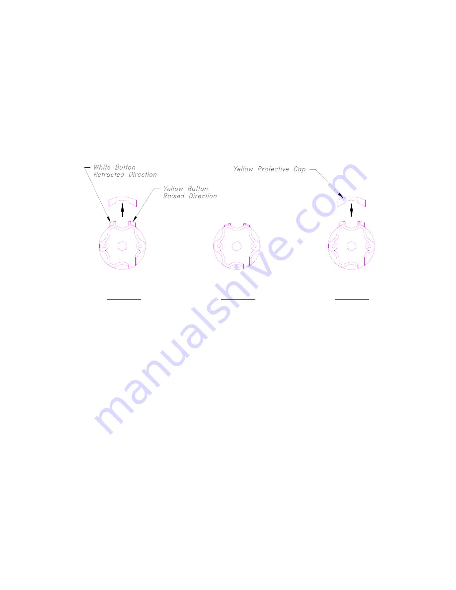
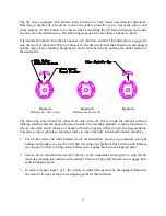
Referring to Figures 4a, 4b and 4c, remove the yellow protective cap to reveal the yellow and
white buttons. Yellow button is for limit switch controlling the lift raised direction and white
button is for retracted direction. The following steps describe how these switches worked.
It is important to know that when a button is out; the limit switch for that direction is engaged to
stop the motor at that point. When a button is in, the limit switch for that direction is disengaged
and the motor is free running. Stopping the motor must be done by pushing the center button on
the transmitter.
Figure
4a Figure
4b Figure
4c
Buttons are shown out
Buttons are shown in
The following steps should be carried out only when the lift is inside the cabinet with the
tabletop attached and the projector placed inside. The traveling platform is spring tensioned to
remove any slack on lift cables so it needs full load to properly define its start and stop positions.
Complete setup weight plays important roll as to where the fully raised and retracted should be.
1 -
Push both yellow and white buttons in, via the transmitter, send an up command (top right
button) and prepare to stop the lift when traveling cage platform flush with inside tabletop
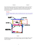
(see Figure 2). Press to bring yellow button out to engage limit switch stopping point.
2 -
Send a down command (lower left button) via the transmitter and prepare to stop the lift
when the tabletop just landed on the cabinet. Press to bring white button out to engage limit
switch stopping point.
3 -
In order to repeat steps 1 or 2, the yellow or white buttons must be disengaged. Otherwise
the motor will stops at the pre-set stopping point for that direction.


