background image

 
107           vwr.com         Instruction manual  VWR

®

 Imager Chemi Premium


The 

Line

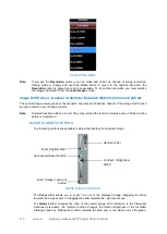
 tool enables you to draw straight lines, at any angle and of any length, on an image. 

Draw the line, then select it using the 

Select

 tool, and the line can be positioned by dragging 

and resized using the visible 'handles'. The line can be coloured and the style of the line can be 
changed using the 

Select Colour

 and 

Select Line Style

 tools. 

The 

Arrow

 tool enables you to draw a straight line with an arrowhead at one end, at any angle 

and of any length, on an image. Draw the arrow, then select it using the 

Select

 tool, and the 

arrow can be positioned by dragging and resized using the visible 'handles'. The arrow can be 
coloured and the style of the arrow can be changed using the 

Select Colour

 and 

Select Line 

Style

 tools. 

The 

Select Colour

 and 

Select Line Style

 tools are used as described above. 

COPY AND PASTE 

The 

Copy and Paste

 function enables you to copy and paste annotations created as described 

above.  If  the  paste  function  is  used  on  the  same  image,  then  the  pasted  annotation  appears 
directly  transposed  over the  top  of  the  source  annotation.  The  pasted  annotation can  then  be 
dragged  to  where  it  is  required  and  modified/changed  as  described  previously.  A  copied 
annotation  can  also  be  pasted  into  a  different  image,  where  it  can  be  modified/changed  as 
described previously. 

To copy an annotation of any type, first select the annotation, then select the 

Copy  Selected 

Annotations

  button 

  .  To  paste  the  copied  annotation,  first  select  the  destination  image, 

then select the 

Paste Annotations

 button 

 . 

EDIT 

The 

Edit

 function enables you to align and delete annotations created as described above. The 

align and delete functions only apply to annotations which have been selected. 

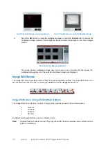
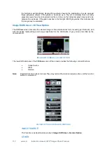
To align annotations, first select the annotations (more than one selection is made by holding 

down the 

Ctrl

 key on the PC keyboard), select the 

Align Selected Annotations

 button 

 , 

then from the drop-down menu select the alignment direction. 


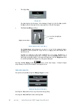
ANNOTATION ALIGNMENT DROP-DOWN MENU 

To  delete  annotations,  first  select  the  annotations,  then  select  the 

Delete  Selected 

Annotations

 button 

 . 

Note:


The 

Delete

 key on the PC keyboard can also be used to delete selected annotations. 

Image Edit Screen - Enhance Option 

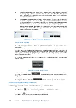
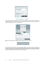
The lower left hand pane of the 

Enhance 

screen provides the following controls/functions: 


Image Source 


Enhancement Tools 


Resolution 

Summary of Contents for 730-1469

Page 1: ...Version 01 Issue 04 2021 Instruction Manual VWR Gel Documentation Imager Chemi Premium EUROPEAN CATALOGUE NUMBER 730 1469 ...

Page 2: ... of Manufacturer Europe VWR International bv Researchpark Haasrode 2020 Geldenaak sebaan 464 B 3001 Leuven 3216385011 http be vwr com UK Importer VWR International Ltd Hunter Boulevard Magna Park Lutterworth Leicestershire LE17 4XN http uk vwr com Country of origin UK ...

Page 3: ... 33 Lights 33 Filters 33 Switching Instrument On 34 Entering Hardware Details 37 Entering Personal Preferences 39 Adjusting Basic Screen Viewing Size 48 Recommended Light Dye Accessory and Other Application Tables 49 Loading Test Samples 50 Black Anti reflective Screen Installed 50 Converter screens 50 Ultra bright Blue Light LED Transilluminator Installed 50 White Light Pad Installed 50 Automatic...

Page 4: ... 97 View Images Screen Image Display Options 97 View Images Screen Combining Single Images into a New Multiplexed Image 101 Image Edit Screen 102 Image Edit Screen Image Editing Main Options 102 Image Edit Screen General Option 103 Image Edit Screen Annotate Option 105 Image Edit Screen Enhance Option 108 Image Edit Screen General Annotate Enhance Options Common Controls 110 Image Edit Screen 3D V...

Page 5: ...njury to yourself or other people in the vicinity e g switch off the mains voltage and remove the mains cord before cleaning Warnings appear below WARNING Switch off the mains voltage and remove the mains cord before cleaning WARNING Ensure that all instrument users read and understand the precautions listed below WARNING You are advised to post a copy of the precautions near to or on the instrume...

Page 6: ...fe if it Shows visible damage Fails to perform the intended measurement Has been subjected to severe transport stresses Has been subjected to prolonged storage in unfavorable conditions Environmental Conditions Imager Chemi Premium Systems should only be used under the following conditions Indoors At altitudes below 2000m In ambient temperatures between 5 C and 40 C With relative humidity below 80...

Page 7: ...prohibited WARNING Ensure that the mains supply socket on the instrument is not obstructed i e leave a gap to allow easy disconnection of the mains cord WARNING If the mains power cord has to be replaced ensure that the replacement cord is appropriately rated and approved for the intended use When working with the Imager Chemi Premium System Connect the instrument to a correctly installed mains po...

Page 8: ...1 2005 AMD1 2009 and AMD2 2013 CSV or equivalent standards Installation Category The instruments are able to withstand transient overvoltages typically present on the mains supply The normal level of transient overvoltages is impulse withstand overvoltage category II of IEC 60664 1 2007 Pollution Degree 2 Normally only non conductive pollution occurs Occasionally however temporary conductivity cau...

Page 9: ...w attention to specific hazards refer to this User Guide and other documentation provided with the instrument for more details concerning potential hazards and any precautions or other actions that must be taken WARNING To prevent potential personal injury and damage to the instrument switch OFF all components in the system and disconnect them from the mains power supply before altering or making ...

Page 10: ...act your local distributor immediately Unpacking the Main Box The Imager Chemi Premium Instrument is packaged in a large carton which is securely strapped Some Instruments may be shipped as a carton only others may be shipped with the carton strapped onto a wooden pallet Accessories are shipped in one or more separate cartons To unpack a typical Imager Chemi Premium Instrument WARNING A Imager Che...

Page 11: ...mager Chemi Premium Open the cardboard carton top flaps Remove the carton and gently lift the Imager Chemi Premium out Attach the camera slide the transilluminator into place and put on the camera cover Imager Chemi Premium ready for use ...

Page 12: ...ead 15 way D type female to 15 way D type male Camera to PC lead USB Mini B to USB Type A Darkroom to PC lead serial lead 9 way D type male to 9 way D type female plus serial USB converter 9 way D type male to USB Type A Pre ordered Emission Filters Pre ordered epi LED Modules in pairs Transilluminator UltraBright LED blue light transilluminator Visible light converter screen Black anti reflective...

Page 13: ...he Darkroom These illuminate the sample from above These are modular units replaceable by the operator UV lamps of known wavelengths 254 nm 302 nm and 365 nm located above the LED light modules on either side of the instrument These illuminate the sample from above Blue LED lights on transilluminators providing side and through lighting of samples UV lights on transilluminators providing side and ...

Page 14: ...e EPI LED white lights EPI UV 302nm EPI red Hi LED EPI blue Hi LED EPI green Hi LED EPI Far Red HI LED EPI IR Hi LED Visible light converter 33 x 31 cm White light pad for visible stains 20 x 14 or 20 x 30 cm UltraBright LED blue light transilluminator 20 x 16 cm Edge lighting unit 26 5 x 20 cm UV transilluminator 302nm 20 x 20 cm Maximum image area cm 30 5 x 22 7 Minimum image area cm 5 0 x 3 7 W...

Page 15: ...ilable Built in light gantries for Hi LED EPI illumination options RGB and IR APPLICATIONS INDEX Imager Chemi Premium DNA gels Protein gels Multiplex gels 3 or more colours Colony counting 2D Gels DIGE Chemiluminescence blots Colorimetric blots Stain free imaging Films IR imaging Bioluminescence GFP plant imaging Gel Doc Image capture Software The Gel Docs image capture software runs in a standard...

Page 16: ...ptimal sample image The database contains information relating to Sample format Gel Blot Other Blot type Chemiluminescence Fluorescence Visible Sample type Protein DNA RNA Matrix type Acrylamide Agarose Dye types Lighting types TYPICAL IMAGER CHEMI PREMIUM FRONT CAMERA COVER INDICATOR LIGHTS DARKROOM DOOR DARKROOM DOOR MANUAL RELEASE BUTTON ...

Page 17: ...r com Instruction manual VWR Imager Chemi Premium TYPICAL IMAGER CHEMIN PREMIUM DARKROOM DOOR OPEN INDICATOR LIGHTS CAMERA MODULE TRANSILLUMINATOR UNIT ELECTROMAGNETIC DOOR CATCH UPPER LIGHT UNITS BOTH SIDES ...

Page 18: ...e associated PC from which the instrument is to be controlled The Gel Doc software can only be installed from a Windows account that has Administrator rights Installation is performed in the following order 1 Run the Set up Program 2 Select the Instrument Hardware Information 3 Select the Installation Folder Destination Location 4 Select the Start Menu Folder 5 Install Device Drivers using the Dev...

Page 19: ... Chemi Premium 9 Click on the Next button The Setup Gel Doc CFR compliance creen will appear Select if running Gel Doc software in a CFR21 part 11 Compliance environment SETUP Gel Doc CFR COMPLIANCE Select the Installation Folder Destination Location SETUP Gel Doc SELECT DESTINATION LOCATION SCREEN 10 Select the folder in which you would like the Gel Doc image capture software to be installed To a...

Page 20: ... Gel Doc program start shortcut to be installed To accept the displayed default folder click on the Next button To choose a different folder click on the Browse button and navigate to the desired folder or create a new folder Then click on the Next button 13 The Ready to Install screen will appear Click on the Install button to start the installation process SETUP Gel Doc SELECT START MENU FOLDER ...

Page 21: ...en will change to the second Device Driver Installation Wizard screen This displays details of the device drivers that have been installed DEVICE DRIVER INSTALLATION WIZARD FINISH SCREEN 16 Click on the Finish button 17 The Setup Completing the Gel doc image capture software Setup Wizard screen will appear This indicates that the installation process has finished successfully SETUP Gel Doc COMPLET...

Page 22: ...d to an external PC running Windows 7 or Windows 8 two levels of operator access are available User and Administrator User accounts have limited privileges within the Gl Doc image capture s software Administrator accounts have full privileges 20 Check your desktop you should have a Gel Doc icon visible i e ...

Page 23: ...o double clicking on a conventional computer mouse Touching and dragging corresponds to scrolling or dragging using a conventional computer mouse Connected PC The keyboard and mouse of an external PC connected to a Imager Chemi Premium Instrument function as normal Instrument Set up Standard Darkroom Make sure that the Laboratory bench is strong enough to support the Imager Chemi Premium Instrumen...

Page 24: ...type connector on the Darkroom Connect the other end of the lead to the 9 way D type connector on the serial USB converter Then connect the converter to a USB Type A connector on the PC Note If the PC has a serial 9 way D type male connecter then the female 9 way D type connector on the Darkroom to PC lead may be connected directly to the PC without attaching the converter Note The Gel Doc softwar...

Page 25: ...V TRANSILLUMINATOR IN THE DARKROOM IMAGER CHEMI PREMIUM Filters The Imager Chemi Premium Instrument is provided with a motor driven rotating Filter Holder This is located in the top of the Instrument such that the filter lenses are positioned directly below the front element of the imaging lens Positions are available for up to seven circular filters to be installed These are numbered 1 7 so that ...

Page 26: ... 9 Using your fingers gently rotate the Filter Holder until the next Filter Slot is accessible and repeat the process until all loose shipped Filters have been installed Note You do not have to rotate the Filter Holder to any specific point once the Machine is powered on it will be automatically indexed to its default position as part of the start up sequence 10 Replace the Lens and Camera Units 1...

Page 27: ... Doc program this button is used to return you to the Home screen Displays the camera resolution the connected hardware and the program title for this particular installation it shows that a Imager Chemi Premium with a 4MP camera is installed and the Gel Doc program is running Displays the icon for accessing System data camera hardware and program version information as shown below WORKFLOW STATUS...

Page 28: ...ss into the automatic image capture process for a Gel sample from Quick access into the automatic image capture process for a Blot sample Accessing manual image capture INFORMATION PANES Displays information or images May be presented in a number of configurations depending on the User s location within the program The Home screen displays Saved Protocols also referred to as User Configurations an...

Page 29: ... undertaken within the program NAVIGATION ICONS Shown here with icon labels displayed Load Images icon to navigate to Load Images screen View Images icon to navigate to View Images screen Settings icon to navigate to User Preferences screen Hardware icon to navigate to Hardware screen Entering Hardware Details Now that you have installed your Imager Chemi Premium Instrument you need to enter the d...

Page 30: ...ave been selected on this first Hardware window select the Save icon 6 Select the Edit Hardware icon to open the Lights Filters screen to programme more options into the software LIGHTS FILTERS SCREEN The Lights Filters screen is used to specify the fixed lighting unit types installed to each side of the Darkroom and also to specify the accessory lighting that is installed on the Darkroom Stage Lo...

Page 31: ...selected on this second Hardware window select the Save icon Note Ensure that you save your selections before you leave the Hardware screen 10 Select the icon to return to the Home screen Entering Personal Preferences Every individual who logs on to a Imager Chemi Premium Instrument can create a customised set of Instrument settings i e a profile which reflects the nature of the work the individua...

Page 32: ...the box to Enable Preview mode for manual and chemi This will turn on the upper white lights to help with sample positioning Select an exposure time the default is 250ms Protocols backup check the box to Enablethe back up of the protocol storage file select the number of backups and the time interval between back ups in days Screen Changing Prompts enables you to turn the screen changing prompts w...

Page 33: ...t If not checked the report contains the image plus some basic information e g filename username date time sample filter etc o Preview Before Printing if the checkbox is checked the screen displays a preview of the report before it is printed If not checked the report is printed without a preview being displayed Quick Quant Report settings select the analysis report setting for all your images o S...

Page 34: ...re Software will then apply this default Dynamic Fielding data set to your captured images when you select the Use Dynamic Fielding checkbox in the Dynamic Fielding box on a Sample Positioning screen If you select the Reset Dynamic Field Data button the following pop up message is displayed RESET DYNAMIC FIELD DATA MESSAGE POP UP o Select the Yes button to perform a Dynamic Fielding operation Foll...

Page 35: ...PREFERENCES CHEMI GENERAL SETTINGS SCREEN CHEMI GENERAL SETTINGS Chemi home settings Show all chemi buttons on home screen There are currently four different ways of capturing a chemiluminescent image Chemi Rapid Chemi single image Chemi series and Signal Accumulation Calculator Show Favourite chemi operation in home screen Select to show your favourite chemi operation in the home screen use the d...

Page 36: ...bines adjacent pixels to form a super pixel but will result in a reduction in resolution Using binning can reduce the exposure time required especially for dyes with an excitation at a longer wavelength CHEMI SINGLE SETTINGS Chemi single settings are split in to two sections chemi Rapid settings and chemi single settings Chemi Rapid settings Select the slider bar position for chemi Rapid exposure ...

Page 37: ...t reagent as default please check the box Alternatively you can select the chemiluminescent reagent you wish to use as default by using the drop down menu Select to Allow binning by Default use the drop down menu to select binning level Binning will increase sensitivity but reduce resolution Enter default values for exposure time Check the box to use the same exposure time for all images Select th...

Page 38: ...box Alternatively you can select the chemiluminescent reagent you wish to use as default by using the drop down menu Select to Allow binning by Default use the drop down menu to select binning level Binning will increase sensitivity but reduce resolution Enter default values for the exposure time settings for the signal accumulation feature for the first and last image Select the number of images ...

Page 39: ...VE AS SETTINGS Select between extended or classical window The extended window will allow you to easily save batches of images whereas the classical window will use the standard windows pop up to export images From the drop down menus select the default file format for export choose from TIFF BMP and JPEG Select the default DPI and the bit depth from the drop down menus Check the box to select all...

Page 40: ... displayed SAVE CHANGES MESSAGE POP UP 4 Select the icon to return to the Home screen Adjusting Basic Screen Viewing Size By default Gel Doc starts up with the display at full screen size The size of the screen display can be adjusted by selecting the Maximise Restore Gel Doc button in the Title Bar and then resizing the display by dragging the dotted arrow icon in the bottom right hand corner HOM...

Page 41: ...i LEDs Anti reflective black screen Red Hi LED Filt705M Far Red HI LED FiltLY700 Green Hi LED Filt605M Blue Hi LED Filt525 IR Hi LED FiltLY800 UV 365nm HI LED FILTUV Visible light Gel e g Coomassie blue and Silver stain Visible Light converter FiltUV Membrane e g Ponceau Red Visible Light converter FiltUV Please note that when imaging EtBr with the Ultra slim blue light LED Transilluminator faint ...

Page 42: ...and Silver stain can be placed directly on top of the transilluminator with the white side facing upwards Blue light conveter screen for imaging Safe Dye gels can be placed directly on top of the transilluminator with the blue side facing upwards Ultra bright Blue Light LED Transilluminator Installed The UltraBright LED blue light Transilluminator if required to be used should be installed in plac...

Page 43: ...elect from Gels or Blots then select your sample from the drop down list Automatic Gel Image Capture DNA RNA Agarose Gel and DNA RNA Acrylamide Gel 1 Select the Gels icon on the Home screen This displays the Gels drop down list GELS DROP DOWN LIST 2 Select your Gel type from the drop down list e g DNA Agarose Gel This displays a Sample Size pop up dialogue box SAMPLE SIZE POP UP ...

Page 44: ... Fluor 488 from the list If multiplexing e g Alexa Fluor 488 and Alexa Fluor 647 you can image up to 5 different dyes at a time depending on your hardware set up Use the green arrow to move forward to the sample positioning screen Note if you get the message You do not have the hardware for this multiplex To find out more contact VWR you may need to purchase additional lighting or filters to be ab...

Page 45: ...rop down list BLOTS DROP DOWN LIST 1 Select your Blot type from the drop down list e g Chemi Rapid 2 Select your sample size from the standards in the pop up menu or enter the dimensions of your sample in the Size boxes in cm 3 On the sample positioning screen adjust the lens controls 4 Close the darkroom door and Gel Doc image capture software will automatically capture your image according to th...

Page 46: ...isible marker Choose between visible marker and marker is colour 8 Select Auto Expose Area if required 9 Press capture to capture an image Note If you have not pressed the capture button straight away after the evaluation time then when you press capture a message will pop up Preview time has expired chemiluminescent signal may have decreased Are you sure you would like to continue Select Yes to c...

Page 47: ...e captured 7 Check the box if you would like to image a visible marker Choose between visible marker and marker is colour 8 Press the capture button to capture the image Fluorescence Blot 1 Select your Blot type from the drop down list e g Fluorescence Blot 2 Select your sample size from the standards in the pop up menu or enter the dimensions of your sample in the Size boxes in cm 3 From the dye ...

Page 48: ...ta This feature will take an image of the membrane after a stain free activated gel has been transferred to a membrane AUTOMATIC IMAGE CAPTURE SAMPLE POSITIONING AND CAPTURE SCREEN SAMPLE POSITIONING At this point the Camera is live and the image it is seeing of your sample is presented in the left hand pane Controls are provided for you to improve this live preview image of your sample enabling y...

Page 49: ...ontrols the amount of light that passes through the lens to the sensor Larger aperture openings smaller f numbers will result in shorter exposure times and smaller aperture openings larger f numbers will result in longer exposure times With Zoom control selected the physical position of the sample relative to the camera is changed allowing the User to concentrate on a smaller area of the sample ma...

Page 50: ...gging the slider towards the sign zooms out Zooming in or magnifying an area of the image allows you to align the sample more accurately using the grid overlay USING DYNAMIC FIELDING TO IMPROVE SAMPLE IMAGE QUALITY The Dynamic Fielding option allows you to correct the image for uneven lighting This can cause problems when quantifying bands or spots across a large sample The image of the dynamic fi...

Page 51: ...nd resized AUTOEXPOSE AREA SELECTOR BOX You also have the option to use the area outside of the yellow box to set the exposure This is useful if the bulk of the image is faint and only a small area contains prominent bands The yellow box can be positioned to contain the prominent bands and then the Use Area Outside ROI checkbox can be checked Exposure will then be based on the area outside the yel...

Page 52: ...entral Image Pool pane As more images are captured these also appear in the Image Pool When initially captured images in the Image Pool are unsaved and are outlined in red UNSAVED IMAGE POOL IMAGE To save the captured image select the image in the Image Pool and select the Save icon Once saved images in the Image Pool are outlined in green and their filename appears below the image SAVED IMAGE POO...

Page 53: ...ny grayscale levels have been captured and the red lines on the histogram graph may need to be adjusted to see bands If the graph reaches to the far right 65535 grayscales this indicates that the image may be saturated IMAGE SLIDER CONTROLS The following controls are available to adjust the way a captured image looks IMAGE SLIDER CONTROLS The Digital Zoom slider allows you to zoom in or out of the...

Page 54: ...changes the image back to normal CAPTURED IMAGE INFORMATION Select the Image Information icon This displays a pop up window displaying captured image information The information displayed is as follows Dye Image capture date time Filter Light Exposure time Iris f number Image size Range range of grey scales captured IMAGE INFORMATION POP UP WINDOW The Image Information icon turns red Selecting the...

Page 55: ...es of your sample with the same or different exposure filter lighting settings for each capture which are then combined into a single combined additive image Multiplex used to capture a series of images up to 5 of your sample with different exposure filter lighting settings for each capture which are then displayed as separate images and as a combined image Used when more than one fluorophore has ...

Page 56: ...Manual Image Capture Additive Series To capture a series of images with different settings for each which will then be displayed as separate images plus a combined image press the Multiplex button See Manual Image Capture Multiplex Manual Image Capture Single Image Note A single image can be captured directly from the basic Manual Capture screen without accessing the Image Capture options 6 Make S...

Page 57: ...DROP DOWN MENU ii Select the Filters button and select your preferred filter from the drop down menu FILTERS DROP DOWN MENU Note On initially calling up the Manual Capture screen the Dynamic Fielding function in the right hand pane will have been displaying the following Once you have made Lighting and Filters selections the Dynamic Fielding function will change to the following ...

Page 58: ... USING THE GRID The Grid button lets you overlay a grid on the image enabling you to better align the sample Use the Door Open button on the right hand side of the Darkroom to open the Darkroom Door slightly to enable you to move the sample around to align it with the grid projection Pressing the Grid button calls up the grid menu o No Grid option removes the grid projection o Show Grid option dis...

Page 59: ...minent bands may be overexposed saturated Select the Select AutoExpose Area button This introduces a yellow selector box onto the sample image The yellow box can be dragged around and resized AUTOEXPOSE AREA SELECTOR BOX You also have the option to use the area outside of the yellow box to set the exposure This is useful if the bulk of the image is faint and only a small area contains prominent ba...

Page 60: ...aller aperture openings larger f numbers will result in longer exposure times With Zoom control selected the physical position of the sample relative to the camera is changed allowing the User to concentrate on a smaller area of the sample maximising resolution This control works by raising lowering the Stage by moving the slider up down or by selecting the buttons 10 Select the Camera resolution ...

Page 61: ...g image saturation This function is useful for quantifying data The following pop up message is displayed as the Instrument makes an image capture AUTO EXPOSING MESSAGE POP UP The Exposure Timing icon appears at the bottom of the screen This changes to display the progress of the exposure as a coloured bar progressing around the icon While the exposure is progressing and this may take several minu...

Page 62: ...button If an image has not been saved you will see a Save prompt SAVE PROMPT i If multiple images are captured without any images being saved multiple images can be selected and saved in a single operation Check the Multi Select Mode checkbox in the Image Pool and select multiple images ii To save the selected images select the Save icon MANUAL CAPTURE SINGLE IMAGE WITH MANUAL EXPOSURE 12a Set an ...

Page 63: ... the image is captured it appears in the left hand pane and also as a thumbnail in the central Image Pool pane If more images are captured these also appear in the Image Pool When initially captured images in the Image Pool are unsaved and are outlined in red UNSAVED IMAGE POOL IMAGE 12c To save a captured image select the image in the Image Pool and select the Save icon Once saved images in the I...

Page 64: ...fine the number of images you want in your series In the right hand pane the Number of images selector is displayed NUMBER OF IMAGES SELECTION 14 Use the buttons to select the number of images you want to capture then select the Next arrow For this example set to 3 by selecting the button You must now define a Camera resolution for your series of images In the right hand pane the Binning selector ...

Page 65: ...nterval time time between captures in the series the exposure times for each image in your series of images and the lighting filter sets for your images The controls for these are displayed in the right hand pane SERIES EXPOSURE CONTROLS FIRST IMAGE SERIES EXPOSURE CONTROLS SECOND IMAGE SAME AS PREVIOUS UNSET ...

Page 66: ... filter selections as described previously 17 Select the Next arrow to make the settings for image 2 Select the Last arrow to apply the settings you have entered for image 1 to all of the remaining images in your series Go to Step 14 18 By default the Same as previous checkbox is checked making the settings for the second image the same as the settings for the first image and the setting boxes are...

Page 67: ...lect Autoexpose Area Lens Controls as described previously 24 Select the Capture button The Exposure Timing icon appears at the bottom of the screen This changes to display the progress of the exposures as concentric coloured bars progressing around the icon While the exposures are progressing and this may take several minutes it is possible to navigate away from the Manual Capture screen and brow...

Page 68: ...ly as a large image in the left hand pane by selecting the desired image from the series of thumbnail images The thumbnail images in the Image pane overlay and partially obscure the main image To view the entire main image select the minimise icon in the top right hand corner above the first thumbnail image This hides the thumbnails leaving just a banner containing a minimise icon Selecting the mi...

Page 69: ...from the Image Capture options You must now define the number of images you want in your series In the right hand pane the Number of images selector is displayed NUMBER OF IMAGES SELECTION 28 Use the buttons to select the number of images you want to capture then select the Next arrow For this example set to 3 by selecting the button You must now define a Camera resolution for your series of image...

Page 70: ...g and Filters functions in the right hand pane to make your lighting and filter selections as described previously 37 Select the Next arrow to make the settings for image 2 Select the Last arrow to apply the settings you have entered for image 1 to all of the remaining images in your series 38 By default the Same as previous checkbox is checked making the settings for the second image the same as ...

Page 71: ...Grid Select Autoexpose Area Lens Controls as described previously 44 Select the Capture button The Exposure Timing icon appears at the bottom of the screen This changes to display the progress of the exposures as concentric coloured bars progressing around the icon While the exposures are progressing and this may take several minutes it is possible to navigate away from the Manual Capture screen a...

Page 72: ... pane changes as each image is captured as each of the newly made captures is added to the main image to produce a combined or additive image Once the series of captures is complete the combined image appears as the main image in the Image pane along with the stack of series captured images and also as a thumbnail in the central Image Pool pane When initially captured images in the Image Pool are ...

Page 73: ...he Image Capture options You must now define the number of images you want in your series In the right hand pane the Number of images selector is displayed NUMBER OF IMAGES SELECTION 47 Use the buttons to select the number of images you want to capture then select the Next arrow For this example set to 3 by selecting the button You must now define a Camera resolution for your series of images In t...

Page 74: ...the most appropriate exposure time for the image Use the Lighting and Filters functions in the right hand pane to make your lighting and filter selections as described previously 50 Select the Next arrow to make the settings for image 2 Select the Last arrow to apply the settings you have entered for image 1 to all of the remaining images in your series 51 Enter the settings for all the images in ...

Page 75: ... browse view and edit previously captured images The Current Protocol display changes as the series of captures is made As a capture is made using a protocol the protocol box is highlighted yellow When the capture is complete a green tick appears inside the protocol box and the yellow highlight is removed The yellow highlight then appears on the next protocol box in the series once that capture ha...

Page 76: ...e thumbnail By default this is the combined image i To make one of the individual capture images in the stack the main image select the drawing side of the thumbnail The yellow highlight will move from the default thumbnail to the selected thumbnail MINIMISE BUTTON ii To view the complete main image in the left hand pane select the Minimise button above the thumbnail stack iii To view the thumbnai...

Page 77: ...GE POOL IMAGE 57 To save a captured image select the image in the Image Pool and select the Save icon Once saved images in the Image Pool are outlined in green and their filename appears below the image SAVED IMAGE POOL IMAGE Images can be dismissed from the Image Pool by selecting them and then selecting the Close button If an image has not been saved you will see a Save prompt ...

Page 78: ...elect Mode checkbox in the Image Pool and select multiple images ii To save the selected images select the Save icon For more information on saving refer to Common Screen Functions and Tools Manual Image Capture Image Actions Following Capture Further actions can be performed on captured images by selecting Image Action icons The function of these is explained in other parts of this User Guide IMA...

Page 79: ...from the Standard View Home screen 1 Work through the following process select the Gels icon select your sample type select your dye position your sample and capture an image 2 Once the image has been captured the Saved Protocols pop up appears SAVED PROTOCOLS POP UP i Select the Yes button The Save Protocol pop up appears SAVE PROTOCOL POP UP ii Follow the prompt in the pop up and either select a...

Page 80: ...Gel Doc to accurately duplicate the Imager Chemi Premium setup you were using when you saved the Protocol each time you use the saved Protocol in the future This checkbox is ticked by default iv Select the OK button to save the Protocol The new saved Protocol Stain free gel appears on the Home screens eg on the Home screen NEW PROTOCOL ADDED TO BOTTOM OF LIST To create a Protocol for a Blot from t...

Page 81: ...c checkbox to make the Protocol accessible to other Users iii Use the Save Lift Position checkbox to save the position of the Stage in the Protocol file This will allow Gel Doc to accurately duplicate the Imager Chemi Premium setup you were using when you saved the Protocol each time you use the saved Protocol in the future This checkbox is ticked by default iv Select the OK button to save the Pro...

Page 82: ...ade to the Configuration Use the Make public checkbox to make the Protocol accessible to other Users iii Use the Save Lift Position checkbox to save the position of the Stage in the Protocol file This will allow Gel Doc to accurately duplicate the Imager Chemi Premium setup you were using when you saved the Protocol each time you use the saved Protocol in the future This checkbox is ticked by defa...

Page 83: ...checkbox to prevent adjustments being made to the Protocol Use the Make public checkbox to make the Protocol accessible to other Users iii Use the Save Lift Position checkbox to save the position of the Stage in the Protocol file This will allow Gel Doc to accurately duplicate the Imager Chemi Premium setup you were using when you saved the Protocol each time you use the saved Protocol in the futu...

Page 84: ...ed Protocols appear on the Home screens HOME SCREEN Opening a Protocol To open and use an existing Protocol from the Home screen 1 On the Home screen select the Protocol you want to use On the Standard View Home screen you can sort and search saved Protocols Sort By options are Last Used Title Author Type Dye Search is by entering text in the Search title here field There is also a Clear button to...

Page 85: ...rotocol from the Home screen 1 Select the Delete Protocol button in the Configuration that you want to delete DELETE CONFIGURATION POP UP 2 In the Delete Protocol pop up select the Yes button 3 The selected Protocol is deleted and is no longer visible on the Home screen Editing a Saved Protocol All accessible previously created and saved Protocols appear on the Home screen HOME SCREEN To edit a pr...

Page 86: ...he Load Images screen LOAD IMAGES SCREEN By default the software navigates to the default save location and displays thumbnail size images of all the saved images at that location The software also maps the current drives that it can detect and connect to and displays this in the standard Windows format in the left hand pane Images saved in other locations can be displayed by navigating to their l...

Page 87: ...mbnail image as shown below MULTIPLEXED IMAGE THUMBNAIL Series images can be identified by a pattern of overlapping images in the top right hand corner of the thumbnail image as shown below SERIES IMAGE THUMBNAIL If more images than can be displayed are available then a scroll bar appears scrolling allows you to display the initially non displayed images Selecting an image or images in the central...

Page 88: ...it screen with the image s selected on the Load Images screen displayed in the Selected Images pane For the actions that can be performed using these screens refer to View Images Screen and Image Edit Screen sections of this Guide View Images Screen The View Images screen is used to view and compare captured images Images can be saved or unsaved The View Images screen can be accessed as follows HO...

Page 89: ...on of the main left hand pane labelled with name given to the multiplexed image file e g composite dylight 680 and 800 sgd in the example above The multiplexed image plus all of its constituent separate image captures if saved are displayed View Images Screen Image Display Options The View Images screen or the images displayed on it can be altered in several ways using the following options Zoom C...

Page 90: ...ual image The Gamma slider changes the tone of the overall image With reference to the histogram mentioned previously the Gamma function changes the relative brightness of the recorded midrange tones by shifting them either towards the dark end or the white end of the graph without changing the extreme dark or extreme white values This gives the recorded image an overall darker or lighter appearan...

Page 91: ...d when the cursor changes hold and drag to move the image around in its viewing window A Histogram button is displayed for each image below the vertical Scroll bar Selecting this displays a histogram or graphical representation of the distribution of grey scales recorded by the camera sensor with black to the extreme left white to the extreme right HISTOGRAM DISPLAY The Histogram button turns red ...

Page 92: ... of how bright highlights are in an image Brightness is a measure of how bright shadows are in an image Use the Contrast slider to control how bright the lightest objects in an image are displayed Use the Brightness slider to control how bright dark objects in an image are displayed Selecting the File Display button when on the View Images Compare Images screen takes you back to the standard View ...

Page 93: ... Action icons at the bottom right of the screen The Multiplexed Image icon only becomes active once files are selected in the View Images main pane Note Selected function buttons turn red They stay red and the function remains active until the function button is re selected To create a new multiplexed image 1 In the Single Images display select the images that you want to combine This function can...

Page 94: ...iplexed image plus all of the selected constituent images are displayed Image Edit Screen The Image Edit screen provides a wide variety of image manipulation options The Image Edit screen can be accessed from other screens by selecting the Edit icon from the Image Action icons Image Edit Screen Image Editing Main Options The Image Edit screen provides a variety of image editing options grouped int...

Page 95: ...General Option The General option provides a range of basic image manipulation tools The lower left hand pane of the General screen provides the following controls functions Image Source Rotation Copy Image Other Note Selected function buttons turn red They stay red and the function remains active until the function button is re selected GENERAL CONTROLS FUNCTIONS IMAGE SOURCE General button Annot...

Page 96: ...e orientation can be reset to its original position by selecting the Reset Rotation button COPY IMAGE An image can be copied to the Windows Clipboard by selecting the Copy button This allows you to paste the image into another package OTHER The Other functions provided are Saturation and Colour The Saturation function can be used to check if areas of the image are going to be over exposed over exp...

Page 97: ...sh makes a protein gel appear silver Coomassie blue and SYPRO red stained If the image being edited is a multiplex image the colour change is applied to all of the individual exposure captures but not the composite image To apply the colour change to the composite image as well check the Use in Composite checkbox Use the colour picker to add a custom colour to a single image Select the Colour Imag...

Page 98: ...ation Tools Copy and Paste Edit Note Selected function buttons turn red They stay red and the function remains active until the function button is re selected ANNOTATE CONTROLS FUNCTIONS IMAGE SOURCE This function is as described previously in Image Edit Screen General Option ANNOTATION TOOLS The following image annotation tools are available Select tool Pan tool Text tool Fill No Fill tool Rectan...

Page 99: ...lique and normal bold The Fill No Fill tool enables you to fill shapes that you have added to the image Select the shape then select a colour for the fill using the Select Colour tool The Rectangle tool enables you to add 4 sided shapes to an image Draw the shape then select it using the Select tool and the shape can be positioned by dragging and resized using the visible handles A rectangle can b...

Page 100: ...op of the source annotation The pasted annotation can then be dragged to where it is required and modified changed as described previously A copied annotation can also be pasted into a different image where it can be modified changed as described previously To copy an annotation of any type first select the annotation then select the Copy Selected Annotations button To paste the copied annotation ...

Page 101: ... applies a smoothing filter to the selected image This can be useful if the image has specks of dust or bubbles present However there may also be a reduction in band sharpness The Invert tool reverses the image i e white appears black black appears white This can be useful when trying to view very faint bands on an image The Speckle Correct tool can be used to remove white speckles or hot pixels f...

Page 102: ...ngle just made and also cancels the selection function Once you have defined the area you want to examine more closely using the Define area to be cropped tool select the Crop area tool to perform the crop function The defined area is cut out of the image the rest of the image is discarded and the cropped or cut out selection is enlarged to the full viewing area RESOLUTION The Resolution tool can ...
Page 103: ...trols Note Selected function buttons turn red They stay red and the function remains active until the function button is re selected IMAGE SLIDER CONTROLS The following controls are available to adjust the display of a captured image IMAGE SLIDER CONTROLS The Zoom slider allows you to zoom in or out of the displayed image Dragging the slider towards the sign zooms in dragging the slider towards th...

Page 104: ...s originally CAPTURED IMAGE INFORMATION Select the Image Information icon This displays a pop up window displaying captured image information The information displayed is as follows Dye Image capture date time Filter Light Exposure time Iris f number Image size Range range of grey scales captured IMAGE INFORMATION POP UP WINDOW The Image Information icon turns red Selecting the Image Information i...

Page 105: ...Edit Screen 3D View Option The 3D View screen presents the selected image in three dimensional form revealing gel thickness and with the peaks representing and being proportional to the distribution of grey scales recorded by the camera sensor IMAGE EDIT SCREEN 3D VIEW OPTION The lower left hand pane of the 3D View version of the screen provides the following controls functions Image Source Other ...

Page 106: ...p up use the slider bars to create a custom colour Press the Reset Colour button to remove the custom colour GAMMA The Gamma slider changes the tone of the overall image With reference to the histogram mentioned previously the Gamma function changes the relative brightness of the recorded midrange tones by shifting them either towards the dark end or the white end of the graph without changing the...

Page 107: ...ewing pane ZOOM SLIDER The Scale control located in the lower left hand corner of the viewing pane increases decreases the vertical axis used to display the distribution of grey scales information SCALE SLIDER Image Edit Screen All Options Common Controls ACTION ICONS All four of the Image Edit main option screens provide the same Action icons across the bottom of the screen The left hand group of...

Page 108: ...previously saved set of annotations SAVE LOAD ANNOTATIONS DIALOGUE BOXES RIGHT HAND PANE The right hand pane of all four of the Image Edit main option screens provides the same information The right hand pane contains the image pool of images selected for editing Each image is displayed in the image pool as a thumbnail If more than one image thumbnail is displayed the currently displayed image is ...

Page 109: ...screen From the pop up save dialog box browse the file saving location and easily edit the file name before saving All images will be saved in the sgd file format which is a VWR data file which contains lots of useful diagnostic information particularly important if you have any support questions N B the windows pop up only appears if you are saving a single image To save batches of images at the ...

Page 110: ... images to the same location each time Note Save selected button will be greyed out until a Save Path has been entered From the save screen the file name can be changed the default is set to the date and time the image was captured To change the file name select the image from the list and type the new file name in the box If you change the file name of an image that has sub images associated to i...

Page 111: ... in the selected range Then select to export as displayed or as captured As displayed will export your image with any edited features you may have performed such as changing the contrast and brightness of an image or if you have rotated or cropped the image As captured will export the image as it was captured You can also from the capture or edit screen check the multi select mode check box and th...

Page 112: ...e path You easily edit the file name of any image selected and if you change the file name of an image that has sub images associated to it Gel doc will automatically change the file name for all the sub images too You can export your images as Tiff bmp or jpeg file formats Select your preferred file format from the drop down list this can also be selected as a default setting in the setting menu ...

Page 113: ...l Report for each test The Full Report content can be controlled using the additional checkboxes check to include the feature Image File Description Capture Properties Basic Report checking this checkbox sets the Instrument to generate a Basic Report for each test Additional features are Basic Report Image Only if the checkbox is checked the printed report contains only the captured image for the ...

Page 114: ...TION 1 From View Images to print the constituent images Select the additive image Select the Print icon The Printing series capture dialogue box is displayed PRINTING SERIES CAPTURE DIALOGUE BOX Select the All button All of the constituent image captures print The additive image does not print OPTION 2 From View Images to print the additive image Select the additive image Select the Print icon The...

Page 115: ...ct any one of the constituent image thumbnails Select the Print icon The Printing series capture dialogue box is displayed PRINTING SERIES CAPTURE DIALOGUE BOX Select the All button All of the constituent image captures print The additive image does not print OPTION 6 From Image Edit to print any one constituent image Select one of the constituent image thumbnails Select the Print icon The Printin...

Page 116: ... select the additive image Select the Print icon The Printing multiplex dialogue box is displayed PRINTING MULTIPLEX CAPTURE DIALOGUE BOX Select the Display button The currently displayed image prints OPTION 3 From View Images to print a single constituent image Select the constituent image Select the Print icon The selected constituent image prints OPTION 4 From View Images to print more than one...

Page 117: ...Select the Print icon The Printing multiplex dialogue box is displayed PRINTING MULTIPLEX CAPTURE DIALOGUE BOX Select the Display button The selected multiplexed image prints OPTION 7 From Image Edit to print the multiplexed image plus the constituent images Select one of the constituent image thumbnails Select the Print icon The Printing multiplex dialogue box is displayed PRINTING MULTIPLEX CAPT...

Page 118: ...the Print icon you can view pages of the report and access the print settings screens using the icons at the top of the screen The following actions are available Zoom in Zoom out No zoom Printer Setup Print Previous Next EXIT WITHOUT PRINTING Having made your selections if for some reason having previewed the report either Full or Basic you do not want to print the report you can exit the Print f...

Page 119: ...ed with biochemical materials reagents e g the interior surfaces of the Darkroom the Black Tray or a transilluminator module can be cleaned using a soft lint free cloth and a non fluorescent cleaning agent such as a neutral detergent or 70 ethanol solution Avoid spilling any liquid into the body of the instrument and clean any external spills immediately If any liquid enters the main body of the i...

Page 120: ...365nm 25x30cm 1 730 1473 Transilluminator VWR 254nm 25x30cm 1 730 1477 Transilluminator VWR 302nm 365nm 25x30cm 1 730 1475 Transilluminator VWR 245nm 302nm 25x30cm 1 730 1481 Transilluminator VWR 254nm 365nm 25x30cm 1 730 1479 Technical service Web Resources Visit the VWR website at www vwr com for Complete technical service contact information Access to the VWR Online Catalogue and information ab...

Page 121: ...r use the Product in its local environment VWR will not be held liable for any related omission or for not obtaining the required approval or authorisation unless any refusal is due to a defect of the product Imager Chemi Premium Troubleshooting PROBLEM POSSIBLE CAUSE SOLUTION Camera not connected or not responding Camera USB cable not plugged in Software driver for the camera is missing Make sure...

Page 122: ...pose of your equipment at lifecycle end by handling it over to an authorized facility for separate collection and recycling It s also your responsibility to decontaminate the equipment in case of biological chemical and or radiological contamination so as to protect from health hazards the persons involved in the disposal and recycling of the equipment For more information about where you can drop...

Page 123: ...and VWR International Ltd VWR International Northern Ireland Ltd Orion Business Campus Northwest Business Park Ballycoolin Dublin 15 Tel 353 01 88 22 222 Email sales ie vwr com Italy VWR International S r l Via San Giusto 85 20153 Milano MI Tel 39 02 3320311 02 487791 Email info it vwr com Korea VWR International 17 Daehak 4 ro Yeongtong gu Suwon si Gyeonggi do Tel 82 31 645 7256 saleskorea avanto...

Reviews: