background image

 VX1828B 


Preliminary Datasheet 

Video Processor for Middle Size LCD Panel 


P.25/P.64 


V1.0 050420 

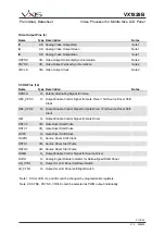
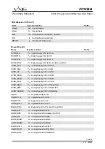
6. REGISTER DESCRIPTION 


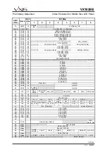
6.1 REGISTER MAP 


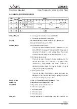
Bit Map


Addr. 
(Hex)


Name


Def. 

(Hex

)


7 6  5  4  3 2 1  0 

01 RST1 - 

RESET 

CLEAR 

02 G1 

8A 

PWDN_at

_CCIR 

AISEL 

05 G4 

D8  - 

MMODE

ML525 MVSTD

MDEFV 

06 AFE0 

28  - 

AFE_SYN

C_EN 

VT VB 

CLAMP_MODE 

07 AFE1 

CA 

STARTUP 

_EN 

PUMP_EN

VCLAMPW CPW_LVL  CPS_LVL 

09 AFE3 

88 

VCLAMP_ 

EN 

VINI CMPLVL 

0A AFE4 

40 

AFE_OFFSET 

0B AFE5 

80 

PUPW 

0C AFE6 

40 

PDNW 

0E TG0 

06 

INV_FLD 

FIX_BLVL

DLDC DCDC  PED 

BLVL_SEL 

0F TG1 

AA  HERRORLIM 

HACCLIM 

VLIMSEL 

VSRSEL 

10 TG2 

20  - 

DVPRES

CLAMPM 

11 TG3 

00 

SPATH 

MAGCY_

EN 

MAGCY 

12 TG4 

15 

SPCTH  - 

STBASE


SEEDCW PHADJ 

13 YC0 

10  - 

LRFDC 

16 YC3 

00  - 

VSHARPNESS 

17 DM0 

79 

PGSTEP  BSYN_SEL DVMASK

CNR DCKILL 

PGSEL 

18 DM1 

20 

MAGCC_ 

EN 

MAGCC 

19 DM2 

55 

ADJSEL 

PC1 PC2 

1A DM3 

00  - 

1B DM4 

40 

BCAGC 

1C CCIR0 

38 

bypass_ 

scaler 

ForceBlue

FVSEL BLUE_EN

TSPD 

1D PADJ00 

00 

1E PADJ01 

80 

BRIGHTNESS 

1F PADJ02 

80 

CONTRAST 

20 PADJ03 

80 

SATURATION 

21 PADJ04 

60 

HUE 

22 PADJ05 

10 BKXON 

BKXAUTO

YDLY 

[2:0] 

CEN 

VNR  UVINV 

23 PADJ06 

46 

BKXLVL 

24 PADJ07 

64 

BKXMAX 

25 PADJ08 

00 

BKXTPIN 

26 PADJ09 

FF 

BKXSLP 

27 (R) 

PADJ0A 

BKXPCONT 

2A TC32 

25 

CPH_MODE[2:0] 

RATE1_CNT_N[4:0] 

2B TC33 

24 

RATE1_PARAM_A[7:0] 

2C TC34 

00 

RATE1_PARAM_A[15:8] 

2D TC35 

00 

RATE1_PARAM_A[23:16] 

2E PEAK1 

20 

PEAK_EN 

PEAK_CLIP_MIN 

2F PEAK2 

00 

PEAK_ADJ1 

30 PEAK3 

00 

PEAK_ADJ2 

31 PEAK4 

00 

PEAK_ADJ3 

32 RGBFIL 

7F 

RGB_ 

FIL_EN 

PEAK_CLIP_MIX 

33 TC36 

00 

RATE1_PARAM_A[31:24] 

34 TC37 

24 

RATE1_PARAM_B[7:0] 

35 TC38 

00 

RATE1_PARAM_B[15:8] 

36 TC39 

00 

RATE1_PARAM_B[23:16] 

37 TC40 

00 

RATE1_PARAM_B[31:24] 

38 TC41 

13 

CPH_DLY[1:0] 

RATE2_CNT_N[4:0] 

Summary of Contents for VX1828B

Page 1: ...Update panel support Headquarters 5F 1 No 9 Prosperity Rd I Science Based Industrial Park Hsin Chu 300 Taiwan R O C Tel 886 3 5630888 Fax 886 3 5630889 Taipei Office 2F 1 No 233 2 Pao Chiao Rd Hsin T...

Page 2: ...VX1828B Preliminary Datasheet Video Processor for Middle Size LCD Panel P 2 P 64 V1 0 050420 Contact VXIS or visit the website to ensure the most recent revision of the document...

Page 3: ...SIENT IMPROVEMENT CTI 15 5 5 LUMA CHROMA ADJUSTMENT 15 5 6 TWO DIMENSIONAL SHARPNESS 16 5 7 BLACK LEVEL EXTENSION BLE 17 5 8 INTERLACE DIGITAL INTERFACE 18 5 9 GAMMA CORRECTION 18 5 10 ON SCREEN DISPL...

Page 4: ...s 49 6 2 13 LINE INVERSION registers 50 4 2 14 Timing Controller registers 51 6 2 15 Status registers 55 6 2 16 PWM registers 56 6 2 17 Continuous Write registers 57 7 ELECTRICAL CHARACTERISTICS 58 7...

Page 5: ...rs for Video Stability Control Frequency Directive 2 D Sharpening Brightness Contrast Color and Tint Adjustments Adaptive Black Level Extension Video Noise Reduction Chrominance Transient Improvement...

Page 6: ...gain control AGC and 10 bit 2 channel AD converters maintain high resolution video quality and with automatic video mode detection user can freely switch and adjust variety of signal source The multip...

Page 7: ...7 P 64 V1 0 050420 3 APPLICATION Video Decoder TV Tuner TV Cable Signal DVD VCD Signal S Video Micro Controller RGB Amplifier General Purpose TCON TCON Vcom Application Circuitry to TFT LCD module 2 W...

Page 8: ...AIC0 AAFOY AAFIY AAFOC AAFIC AIY3 DVDDP5 XTALI XTALO DGNDP5 AVDD_AFE AGND_AFE AVDD_PLL1 AIC1 IR AGND_PLL1 DGND_PLL1 DVDD_PLL1 LPFI LPFO SDA SCL N C N C AVDD_SHIELD DVDDC4 OE3_CPH3 OOEH DVDDC3 CCIR6 H...

Page 9: ...PLL2 58 OSTH1 83 DGNDP3 9 AVDD_PLL1 34 AGND_PLL2 59 OSTH2 84 DVDDP3 10 AGND_PLL1 35 N C 60 DGNDC1 85 CCIR5 11 AAFIC 36 LPFI 61 DVDDC1 86 CCIR4 12 AAFOC 37 AVDD_DACL 62 OCPH1 87 CCIR3 13 AIC0 38 AGND_D...

Page 10: ...er of Y channel AAFOC AO Analog Signal to Optional External Anti Alias Filter of C channel AAFIY AI Analog Signal from Optional External Anti Alias Filter of Y channel AAFIC AI Analog Signal from Opti...

Page 11: ...river 3rd Source Driver Shift Clock OE2_CPH2 O1 Output Enable Control Signal for Gate Driver 2nd Source Driver Shift Clock OE1 O1 Output Enable Control Signal for Gate Driver OSTV2 I O1 Gate Driver St...

Page 12: ...3V for AFE AVDD_AD P33 Analog Supply 3 3V for ADC AVDD_BIAS1 P33 Analog Supply 3 3V for BIAS AVDD_BIAS2 P33 Analog Supply 3 3V for BIAS AVDD_PLL2 P33 Analog Supply 3 3V for PLL2 AVDD_DACL P33 Analog...

Page 13: ...t Input IS 5V Tolerant Schmitt Trigger Input IPU 5V Tolerant Input with Internal Pull Up Resistor IPD 5V Tolerant Input with Internal Pull Down Resistor O1 TTL Output Group 1 4 mA OTS1 Tri State Outpu...

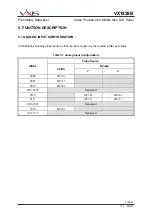
Page 14: ...OG INPUT CONFIGURATION VX1828B has 6 analog video input pins that can be configured by the register AISEL as follows Table 5 1 Analog Input Configurations Video Source S Video AISEL CVBS Y C 0000 AIY...

Page 15: ...N 1 0 PAL M 1 1 NTSC 5 4 COLOR TRANSIENT IMPROVEMENT CTI The color transient improvement CTI engine in VX1828B works adaptively to sharpen the transition of chrominance edges to perform sharp and kee...

Page 16: ...uency response in horizontal sharpness engine The gain for each filter is adjustable from 0 to 14 dB and individually controlled with registers PEAK_ADJ1 PEAK_ADJ2 and PEAK_ADJ3 Figure 5 1 The clippin...

Page 17: ...rent and noticeable to the viewers The BLE function works adaptively depending on the average luminance of the picture The Luminance transform function for BLE is controlled by three parameters BKXLVL...

Page 18: ...TART OF DIGITAL LINE START OF ACTIVE DIGITAL LINE HSYNC SIGNAL NEXT LINE CCIR 656 8 bit parallel interface data format for 525 60 video systems F F 0 0 0 0 X 0 8 0 1 0 8 0 1 0 8 0 1 0 F F 0 0 0 0 X 0...

Page 19: ...points are calculated from linear interpolation 0 8 16 24 32 40 48 232 240 248 256 Input Luminance Output Luminance CLUTABLE03 CLUTABLE02 CLUTABLE32 CLUTABLE31 CLUTABLE30 CLUTABLE29 CLUTABLE06 CLUTAB...

Page 20: ...ma 1 2 1Fh LCD Panel 3 17h Gamma 1 3 5 10 ON SCREEN DISPLAY OSD 5 10 1 OSD INTRODUCTIONS The VX1828B integrates VXIS s font based on screen display OSD unit which can display a total of up to 256 char...

Page 21: ...through registers Table 5 4 Each displaying block cannot be overlapped with others For details of the register setting check OSD section in register description chapter Table 5 4 Position and Size Re...

Page 22: ...acter Index Hex 40h 41h 42h 43h 44h 45h 46h 47h 48h 49h 4Ah 4Bh 4Ch 4Dh 4Eh 4Fh Character Index Hex 50h 51h 52h 53h 54h 55h 56h 57h 58h 59h 5Ah 5Bh 5Ch 5Dh 5Eh 5Fh Character Index Hex 60h 61h 62h 63h...

Page 23: ...ocated according to the registers OSDC_START 5Fh 7 0 and OSDB_START 6Dh 7 0 For example Figure 5 5 if we would like to show VXIS as the title block Hello as the content block and OK as the bottom bloc...

Page 24: ...OSTV2 OSTV1 OCPV OCPH1 OSTH1 OSTH2 OOEH UD_CTRL and LR_CTRL can be independently programmed to open drain output pads Under open drain output mode an external pull up resistor is required 5 12 PULSE W...

Page 25: ...TEP BSYN_SEL DVMASK CNR DCKILL PGSEL 18 DM1 20 MAGCC_ EN MAGCC 19 DM2 55 ADJSEL PC1 PC2 1A DM3 00 1B DM4 40 BCAGC 1C CCIR0 38 bypass_ scaler ForceBlue FVSEL BLUE_EN TSPD 1D PADJ00 00 1E PADJ01 80 BRIG...

Page 26: ...OSDT_SIZEX 55 OSD5 00 OSDT_HLSTART 56 OSD6 00 OSDT_HLSTOP 57 OSD7 00 OSDT_BLSTART 58 OSD8 00 OSDT_BLSTOP 59 OSD9 28 OSDT_POSX 5A OSD10 10 OSDT_POSY 5B OSD11 82 OSDT_BGCLR OSDT_FGCLR 5C OSD12 B4 OSDT_H...

Page 27: ..._RATIO B5 OSB5 80 G_RATIO B6 OSB6 80 B_RATIO B7 OSB7 00 R_BIAS_N B8 OSB8 00 G_BIAS_N B9 OSB9 00 B_BIAS_N BA OSBA 80 R_RATIO_N BB OSBB 80 G_RATIO_N BC OSBC 80 B_RATIO_N BD OSBD 00 RGB_SEL GAIN_R BE OSB...

Page 28: ...D40 00 OSD_FONT_DATA 15 8 DF OSD41 00 OSD_FONT_DATA 7 0 E0 PWM1 FF PWM1_L0 E1 PWM2 FF PWM1_L1 E2 PWM3 FF PWM1_H0 E3 PWM4 FF PWM1_H1 E4 PWM5 FF PWM2_L0 E5 PWM6 FF PWM2_L1 E6 PWM7 FF PWM2_H0 E7 PWM8 FF...

Page 29: ...rs by writing A5h PWDN_at_CCIR Power down decoder circuit at CCIR input mode AISEL Analog video input selection df 1010 Video Source S Video AISEL CVBS Y C 0000 AIY 0 0001 AIY 1 0010 AIY 2 0011 0101 R...

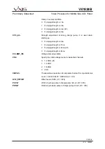
Page 30: ...VX1828B Preliminary Datasheet Video Processor for Middle Size LCD Panel P 30 P 64 V1 0 050420 MDEFV 0 Startup mode selection control for NTSC region 1 Startup mode selection control for PAL region...

Page 31: ...l is set by charge pump clamping of C channel is set by voltage driver The unused channel is fixed at voltage level specified by VINI 1 0 df 10 Enhanced clamp mode The sync tip level of active Y chann...

Page 32: ...0 Pumping strength is 8 lw 1 Pumping strength is 16 lw 2 Pumping strength is 32 lw df 3 Pumping strength is 64 lw VCLAMP_EN Voltage clamping enable VINI Specify the initial voltage level of unselected...

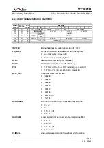
Page 33: ...of blank level while removing the sync tip 0 Automatic detected level df 1 Blank level specified by M_BLVL DLDC Disable luma digital clamp df Enable DCDC Disable chroma digital clamp df Enable PED 0...

Page 34: ...ation 0 6 df 1 16 MAGCY_EN Enable manual setting AGC of luma channel df OFF MAGCY Value of manual setting AGC of luma channel SPCTH Spike count threshold for video noise estimation 0 32 df 1 48 STBASE...

Page 35: ...VX1828B Preliminary Datasheet Video Processor for Middle Size LCD Panel P 35 P 64 V1 0 050420 BLVL_STEP Blank level tracking step in manual selection mode M_BLVL Specify black level when FIX_BLVL 1...

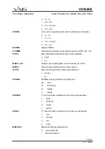
Page 36: ...50420 6 2 5 YC SEPARATION REGISTERS Bit Map Addr Hex Name Def Hex 7 6 5 4 3 2 1 0 13 YC0 10 LRFDC 16 YC3 00 VSHARPNESS LRFDC Left and right pixel fading control VSHARPNESS Vertical sharpness enhanceme...

Page 37: ...gy 1 Line length locking strategy df DVMASK Video mask during vertical blanking period enable df Enable CNR Color noise reduction enable If set successive lines of Cr Cb are averaged For PAL cancels a...

Page 38: ...heet Video Processor for Middle Size LCD Panel P 38 P 64 V1 0 050420 1 512 df 2 1024 3 2048 PC2 2nd order loop filter coefficient for chroma synchronization 0 1 1 2 df 2 4 3 8 BCAGC Burst error gain f...

Page 39: ...Speed of Blue Screen TSPD Transition Criteria 0 Immediately change to blue when VPRES 0 1 Wait 8 field to change to blue after VPRES 0 2 Wait 16 field to change to blue after VPRES 0 3 Wait 24 field...

Page 40: ...synchronization format 0 Equaled VSYNC 262 5 HSYNC per VSYNC df 1 Non equaled VSYNC 262 263 HSYNC per VSYNC 2 Equaled FIELD 262 5 HSYNC per FIELD 3 Non equaled FIELD 262 263 HSYNC per FIELD hsyncip 0...

Page 41: ...heet Video Processor for Middle Size LCD Panel P 41 P 64 V1 0 050420 8 1 2 ns 8 1 2 ns 9 2 4 ns 9 2 4 ns 10 3 6 ns 10 3 6 ns 11 4 8 ns 11 4 8 ns 12 6 0 ns 12 6 0 ns 13 7 2 ns 13 7 2 ns 14 8 4 ns 14 8...

Page 42: ...adjustment SATURATION Saturation adjustment HUE Hue adjustment YDLY Y channel delay control CEN Color transient improvement CTI enable 0 CTI enable df 1 CTI disable VNR Video noise reduction VNR enabl...

Page 43: ...AK4 00 PEAK_ADJ3 32 RGBFIL 7F RGB_ FIL_EN PEAK_CLIP_MIX PEAK_EN Horizontal sharpening enable PEAK_CLIP_MIN Clipping filter parameter PEAK_ADJ1 Weighting of horizontal video sharpening in high frequenc...

Page 44: ...Vsync outputs high impedance enable HS_WIDTH Width of video output horizontal synchronization Actual synchronization width 13 HS_WIDTH x 4 in pixels VS_WIDTH Width of video output vertical synchroniz...

Page 45: ...olor OSD OSD_ALPHA Color Video Color Displaying OSD OSDT_EN OSD title block display enable OSDC_EN OSD content block display enable OSDB_EN OSD bar block display enable Bit Map Addr Hex Name Def Hex 7...

Page 46: ...GCLR OSD title block background color selection see Table 6 2 11 1 for details Table 6 2 11 1 OSD Color Assignment Color Bits Color Color Bits Color 0000 Black 1000 Transparent 0001 Blue 1001 Royal Bl...

Page 47: ...ck highlight vertical stop position OSDC_HLX_START OSD content block highlight horizontal start position OSDC_HLX_STOP OSD content block highlight horizontal stop position OSDC_BLY_START OSD content b...

Page 48: ...ART OSD bar block blink start position OSDB_BLSTOP OSD bar block blink stop position Bit Map Addr Hex Name Def Hex 7 6 5 4 3 2 1 0 74 OSD36 79 OSDB_BGCLR OSDB_FGCLR 75 OSD37 3E OSDB_HLBGCLR OSDB_HLFGC...

Page 49: ...amma enable df OFF CLUTABLE_PGR EZ Gamma programming selection Default is 18h For detail see Table 6 2 12 1 Table 6 2 12 1 CLUTABLE_PGR Value Function CLUTABLE_PGR Value Function 00h 0Fh Using user pr...

Page 50: ...ple GAIN_B INV_FRP FRP polarity R_BIAS G_BIAS B_BIAS R_RATIO G_RATIO B_RATIO R_BIAS_N G_BIAS_N B_BIAS_N R_RATIO_N G_RATIO_N B_RATIO_N Output RGB bias and ratio adjustment RGB_SEL RGB output pin select...

Page 51: ...nd OE3 Q1H_INV To change polarity of Pin OQ1H OEH_SEL 0 OOEH edge trigger 1 OOEH active low df LNR 0 Left right reverse 1 Normal scan df UND 0 Up side down 1 Normal scan df POLS_INV To change polarity...

Page 52: ...PV double 100 SHARP mode 101 NEC mode Bit Map Addr Hex Name Def Hex 7 6 5 4 3 2 1 0 C2 TC6 18 STV_ON CC TC7 06 STV_START CD TC8 10 STV_END AD TC9 6D OEV_START AE TC10 14 OEV_END AF TC11 14 OEV_MASK_ST...

Page 53: ...C3 TC21 0A POL_INV_ON A3 TC22 15 OEH_START A4 TC23 23 OEH_END A5 TC24 00 STH_ON 10 8 A6 TC25 74 STH_ON 7 0 POL_INV_ON OPOLS alternating polarity time OEH_START OEH pulse starting point OEH_END OEH pu...

Page 54: ...6 4A TC45 00 RATE2_PARAM_A 31 24 4B TC46 49 RATE2_PARAM_B 7 0 4C TC47 48 RATE2_PARAM_B 15 8 4D TC48 02 RATE2_PARAM_B 24 16 4E TC49 00 RATE2_PARAM_B 31 24 CPH_DLY 1 0 To set clock phases of CPH2 and CP...

Page 55: ...ching signal of PAL signal IS443 Carrier frequency detection 0 3 58 MHz 1 4 43 MHz VPRES Coarse lock status Set when sync of proper height and duration has been detected on 32 successive lines reset i...

Page 56: ..._H0 E3 PWM4 FF PWM1_H1 E4 PWM5 FF PWM2_L0 E5 PWM6 FF PWM2_L1 E6 PWM7 FF PWM2_H0 E7 PWM8 FF PWM2_H1 PWM_SEL select sel_pwm1 sel_pwm2 sel_pwm3 output source 00 sel_pwm1 vsync_vga sel_pwm2 hsync_vga sel_...

Page 57: ...me Def Hex 7 6 5 4 3 2 1 0 FD CW0 00 CW_DEST 2 0 CW_INIT_ADDR 9 8 FE CW1 00 CW_INIT_ADDR 7 0 FF CW2 00 CW_DATA CW_DEST Continuous write destination selection 0 None 1 OSD command memory 2 OSD font mem...

Page 58: ...ID 0 5 VDDD 0 5 V Input Voltage For Analog Core VIA 0 5 VDDA 0 5 V Junction Temperature TJ 40 125 C Storage Temperature TSTG 55 125 C Lead Temperature Vapor Phase Soldering 40 Seconds TL 215 C Electro...

Page 59: ...t O1 OTS1 High Level Output Voltage VOH 2 4 V Low Level Output Voltage VOL 0 4 V Tri State Output Leakage Current IL 25 25 A Input TTL Output I O1 I O2 High Level Input Voltage VIH 0 65 VDDD V Low Lev...

Page 60: ...ram Resolution 6 bit Gain Range 1 6 ADC Resolution 10 bit Sampling frequency 40 MHz 7 5 DAC SPECIFICATION Parameter Symbol Min Typ Max Unit Resolution 10 Bit Spurious Free Dynamic Range SFDR 61 dB Sig...

Page 61: ...ion time TVICKT 5 ns Output Clock Video output clock VOCLK2 frequency FVOCK 27 MHz Video output clock VOCLK period TVOCK 37 04 ns Video output clock VOCLK width high TVOCKH 18 52 ns Video output clock...

Page 62: ...l Bus Free Time Between STOP and START Condition TBUF 4 7 s Serial Bus Hold Time For START Condition THDSTA 4 0 s SCL Clock Width Low TSCLL 4 7 s SCL Clock Width High TSCLH 4 0 s Serial Data Setup Tim...

Page 63: ...57 58 59 67 73 74 TM0 100nF BEAD to Panel Application Circuit 92 9 16 23 66 27 84 56 28 1 61 70 7 26 3 15 24 29 8 30 25 34 55 60 65 69 79 83 51 50 49 Lumiance Input Chrominance Input 13 20MHz Luma Ant...

Page 64: ...dle Size LCD Panel P 64 P 64 V1 0 050420 9 PACKAGE DIMENSION VXIS Technology Corp http www vxis com 5F 1 No 9 Prosperity Road I Science Based Industrial Park Hsinchu City Taiwan 300 R O C Tel 886 3 56...

Reviews: