


VXL Instruments Ltd
.
Itona TC61yy/TC63yy
Hardware User’s Guide
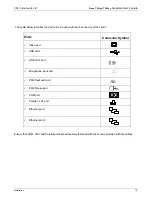
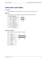
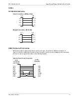
Connectors and Cables
12
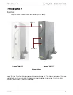
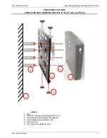
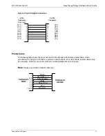
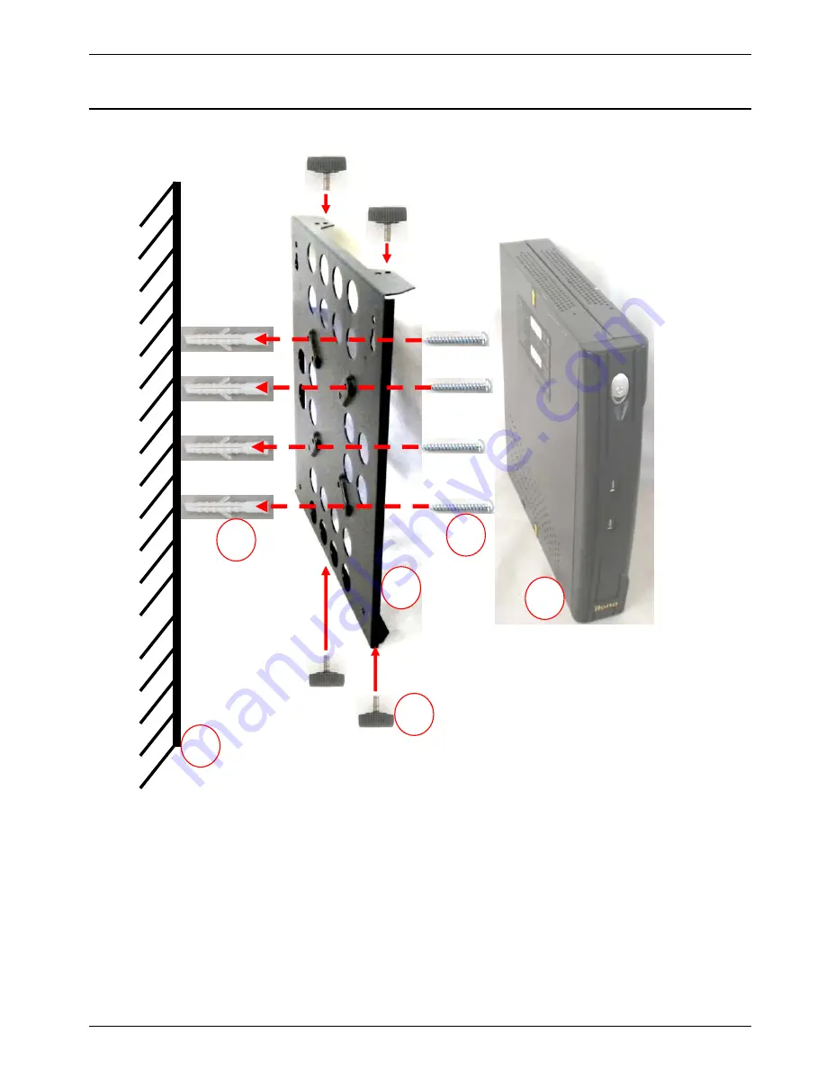
PROCEDURE FOR FIXING
SINGLE SIDE WALL MOUNTING BRACKET for Itona TC61yy and TC63yy
STEPS
1. Wall
2. Drill holes and Insert Wall Plug M7x33, 4no
3. Place Single Side Wall Mounting Bracket
4. Fix Self taped Screws M4x24, 4no
5. Place the Unit
6. Fix Thumb Screws M3x8, 4nos
5
1
4
2
3
6