Page 12 of 48
PAM-199-P
4.3
Control of directional valves (195)
4.3.1 Typical system structures
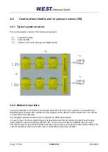
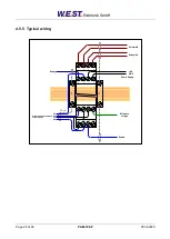
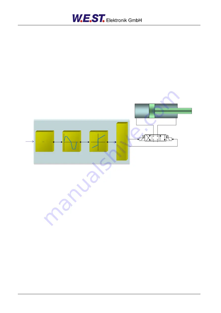
This minimal system consists of the following components:
(*1)
proportional valve
(*2)
hydraulic cylinder
(*3)
power amplifier
(*4)
interface to PLC with analogue and digital signals
4.3.2 Method of operation
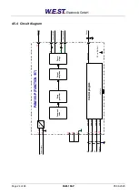
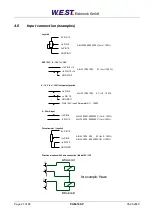
This power amplifier is controlled by an analogue signal (from the PLC, from a joystick or a potentiometer). An
ENABLE signal (typically 24V) activates the module and the READY output indicates this, if no internal or ex-
ternal error was detected.
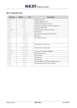
The integrated standard functions will be configured via different parameters.
In case of a fault, the power output stage will be deactivated and the fault will be indicated through a deac-
tivated READY output and a flashing READY LED. To leave the error state the ENABLE has to be reset.
The output current is closed loop controlled whereby a high accuracy and a good dynamic will be obtained. All
custom proportional valves (up to 2.6A) may be controlled with this power amplifier.
T
A
B
P
P
O
W
E
R
S
T
A
G
E
MINMAX
RAMP
INPUT
c
x
b
a
y
PL
C
/
SPS
*1
*2
*4
*3


