Page 23 of 48
PAM-199-P
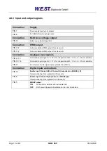
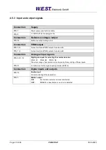
4.5.3 Input and output signals
Connection
Supply
PIN 7
Power supply (see technical data)
PIN 8
0 V (GND) Power supply (ground).
Connection
Reference voltages output
PIN 12
Reference output voltage (8 V).
Connection
PWM output
PIN 3 / 4
Current controlled PWM outputs for solenoid A
PIN 1 / 2
Current controlled PWM outputs for solenoid B.
Connection
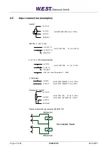
Analogue input signals
PIN 6 / 9 / 14
Digital gate inputs for selecting the command value:
PIN 6: S1 PIN 9: S2 PIN 14: S4
The whole range of set points can be chosen by binary coding of these inputs.
PIN 11
0 V reference for the signal inputs (potential of PIN 8).
Connection
Digital inputs and outputs
PIN 15
Enable Input
:
General enabling of the application.
PIN 5
READY output
:
ON:
No internal or external errors are detected
OFF:
ENABLE is deactivated or an error is detected


