background image

13

© W

&

W 08/2016 Version 7

ID32907

5.2.8 Compensating unevenness 

If there is an unevenness on the floor compensating plates must be fixed to make sure 

that the ladder stands safely. 

Unevenness bigger than 1cm must be compensated by the customer himself.

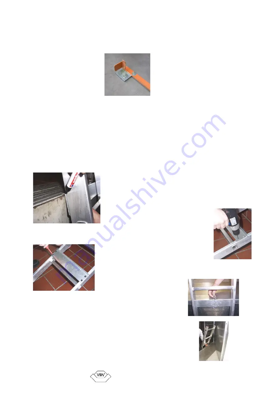
Mounting example for compensating plates

5.3 Door sill holder ZUBESET-B pit ladder

The door sill holder must be mounted to the ladder if the ladder is leaned against the 

sill. The sill holder secures the ladder against tilting to one side while descending.


5.3.1. Put the ladder into the previously mounted floor attachment and lean the ladder 

against the sill. 


5.3.2. Slide the sill holder between the ladder and the sill, so that its shorter angled side 

lies on the sill.

5.3.3. Push the sill holder firmly against the ladder and pull 

the ladder aback, so that you can mark the drill holes for the 

sill holder on the ladder.

5.3.4 Drill the holes into the ladder with the provided 3,5mm drill.

5.3.5. Fix the sill holder to the ladder with the provided tapping 

screws.

5.3.5 Secure the ladder with the lock bolt at the revol-

ving doors

In the shorter angled part of the sill holder is a drilling. 

Optionally a 6mm hole can be drilled through this into 

the sill where the bolt affixed to the chain can be put in. 

So the ladder is secure against unintended backsliding.

Summary of Contents for 78300

Page 1: ...ZUBESET A und B Leitertyp 2 mit ZUBESET B Leitertyp 3 mit ZUBESET B Leitertyp 4 mit ZUBESET B Leitertyp 5 Mounting instruction Ladder type 1 5 Ladder type 1 with ZUBESET A and B Ladder type 2 with ZUB...

Page 2: ...erwendung Leitertyp 1 4 Sprossenanlegeleiter mit allgemeiner Verwendung Bei Einsatz als Gru benabstiegsleiter ist das ZUBESET B erforderlich Die Schachtgrube darf max 2 8m tief sein Leitertyp 5 Gruben...

Page 3: ...en M10x70 8x Unterlegscheiben M10 2x D bel 14x75 ACHTUNG Zur fachgerechten Nutzung der Leiter muss die auf jeder Leiter angebrachte Betriebsanleitung beachtet werden ACHTUNG Die Leitertypen 1 4 d rfen...

Page 4: ...m Leiterkette 1x Wandaufh ngung inkl berwachungskontakt 2x 6Kt Holzschraube M10x70 2x D bel M14 8x Unterlegscheibe M10 4 6 Leiter ZUBESET A 1x Wandaufh ngung 2x 6Kt Holzschraube M10x70 2x D bel M14 8x...

Page 5: ...ufh ngung mit Kontakt berwachung Installieren Sie den Schalter zur berwachung der Wandauf h ngung fachgerecht in Reihe zum Notbremsschalter des Sicherheitskreises der Aufzugsteuerung Der Schalter hat...

Page 6: ...t einem 14er Bohrer 5 2 6 Bei Hydraulikaufz gen dichten Sie die D bel mit der beiliegenden Dichtungsmasse ab 5 2 7 Schrauben Sie die Bodensicherung am Boden fest 5 2 Bodensicherung ZUBESET B Grubenabs...

Page 7: ...hieben Sie den T rschwellenhalter von oben zwischen Leiter und T rschwelle so dass er mit der kurzen abgewinkelten Seite auf der T rschwelle aufliegt 5 3 3 Halten Sie den T rschwellenhalter fest gegen...

Page 8: ...this mounting instruction have the following denotations 2 Intended use Ladder type 1 4 Rung ladder for general use When using it as a pit ladder ZUBESET B is necessary Maximum pit depth 2 8m Ladder...

Page 9: ...f there is an emergency brake switch ATTENTION If ladders are mounted in lift shafts the ladder and its attachments must not extend into the moving parts of the lift 4 Scope of delivery 4 1 Ladder typ...

Page 10: ...1x 3m chain for the ladder 1x Wall attachment incl monitoring contact 2x Wood screws M10x70 2x Dowels M14 8x Washers M10 4 6 Ladder ZUBESET A 1x Wall attachment 2x Wood screws M10x70 2x Dowels M14 8x...

Page 11: ...it of the lift control system The rated current of the switch is 3A at AC15 250V 50Hz and 3A at DC13 24V 5 1 7 Wall attachment with U lock or triangular lock Hook the ladder into the attachment to mak...

Page 12: ...l the holes with a 14 drill 5 2 6 For hydraulic lifts seal the dowels with the provided sealing compound 5 2 7 Screw the floor attachment to the bottom 5 2 Floor attachment ZUBESET B pit ladder 5 2 1...

Page 13: ...d floor attachment and lean the ladder against the sill 5 3 2 Slide the sill holder between the ladder and the sill so that its shorter angled side lies on the sill 5 3 3 Push the sill holder firmly a...

Reviews: