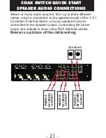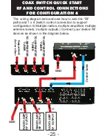
INPUT AMP KEYING
OUTPUT AMP KEYING
A
B
C
1
2
3
3 x 1 CONTROLLER/SWITCH
REAR PANEL CONTROLS
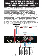
These (RCA) amplifier keying
inputs accept linear amplifier
keying connections from up
to 3 radios. The output amplifier keying connectors support
keying up to 3 amplifiers. Each 3 X 1 Controller amplifier
keying outputs is connected to an internal controller relay
contact. The specific output amplifier (RCA) keying contact
that is closed is associated with the RF output that is
being selected by the front panel output select switches.
(see page 5).
The following is an example of how the amplifier keying
works. When RF Output 3 is being selected, on the 3 X 1
controller, the green LED for output 3 will be on. If RF
Output 1 is selected then Output AMP Keying Output 1 will
be shorted. If RF Output 2 is selected then Output AMP
Keying Output 2 will be shorted. If RF Output 3 is selected
then Output AMP Keying Output 3 will be shorted.
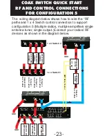
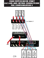
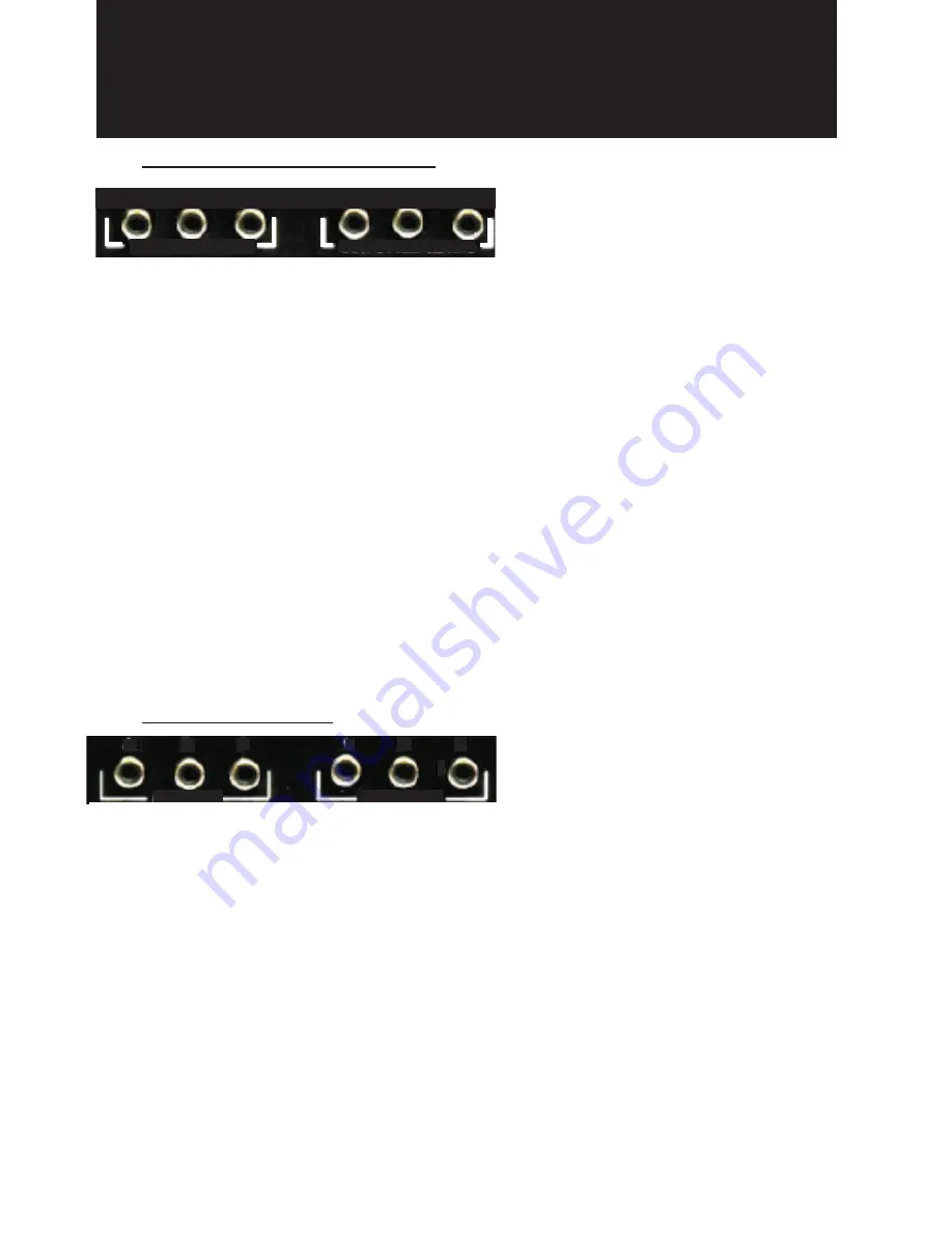
These RCA connectors are
used to connect ALC function
between amplifiers and radios.
The radio connected to Input A should connect its ALC input
into (RCA) ALC input A. The radio connected to Input B
should connect its ALC input into (RCA) ALC input B. The
radio connected to Input C should connect its ALC input into
(RCA) ALC input C. The amplifier connected to 1 X 4 Antenna
Switch Output 1 should connect its ALC to ( RCA) Output ALC
1.The amplifier connected to 1 X 4 Antenna Switch Output 2
should connect its ALC output to (RCA) Output ALC 2. The
amplifier connected to 1 X 4 Antenna Switch Output 3 should
connect its ALC output to (RCA) Output ALC 3. Which one of
three RCA ALC outputs a given ALC input is connected is
associated with the RF output that is being selected by the
front panel RF Output select switches. (see page 5).
Linear Amplifier Keying
ALC CONTROL
A
B
C
INPUT ALC
OUTPUT ALC
1
2
3
-10-


