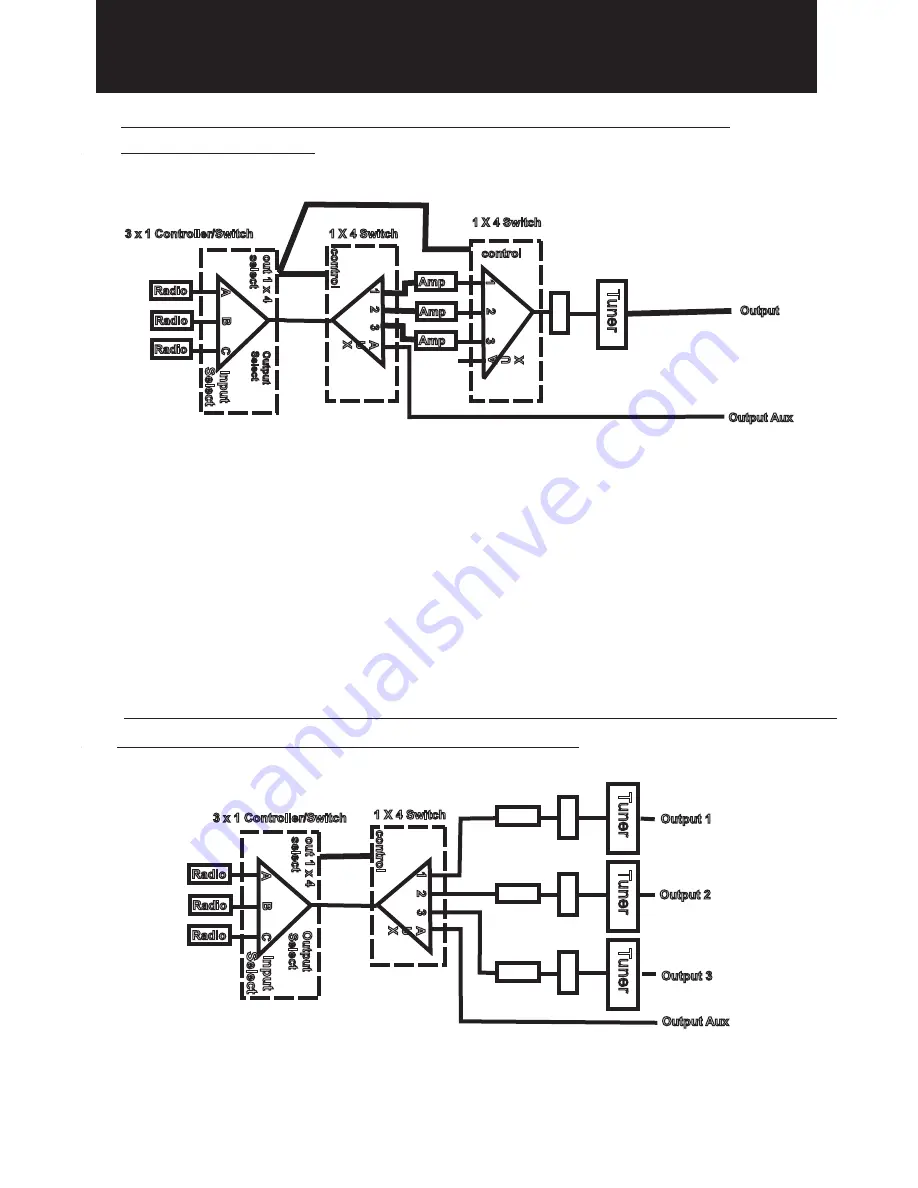
COAX SWITCH CONFIGURATIONS
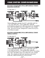
Configuration 5
The front
panel AUX switch may not be used, in this configuration, to
connect an external antenna or dummy load to the AUX
AUX OUTPUT for use by the connected amplifiers.
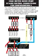
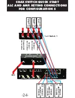
This configuration requires one 3 X1 controllers and two
1 X4 Coax Switches. This configuration supports
connecting any one up to 3 radios to any one of 3 amplifiers.
Any of the 3 amplifiers may be configured to use a single
tuner. The selected amplifier and/ tuner may be connected to
a single antenna, antenna switches or other device.
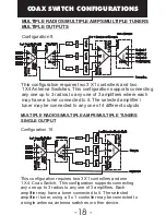
MULTIPLE RADIOS/MULTIPLE AMPS/SINGLE TUNER/
SINGLE OUTPUT
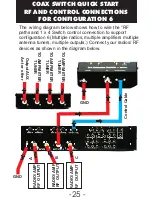
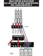
Configuration 6
This configurations connects up to 3 radios to any one of 3
linear amplifiers with their own tuners. The output(s) of each
tuner is connected to an antenna, antenna switches or other
device.
MULTIPLE RADIOS/MULTIPLE AMPS/MULTIPLE TUNERS/
OUTPUTS CONNECTED TO TUNERS
Radio
A
1
control
Output
Select
out1x4
select
3 x 1 Controller/Switch
1 X 4 Switch
2
3
A
U
X
B
C
Radio
Radio
1x4
3x1
Amp
1
Output Aux
Output
control
1 X 4 Switch
A
U
X
2
3
Amp
Amp
1x4
Meter
T
uner
Input
Select
Radio
A
Output 1
Output 2
Output 3
Output Aux
1
control
out1x4
select
Output
Select
3 x 1 Controller/Switch
1 X 4 Switch
2
3
A
U
X
B
C
Radio
Radio
1x4
3x1
Meter
Meter
Meter
T
uner
T
uner
T
uner
AMP.
AMP.
AMP.
Input
Select
-16 -


