background image


Page 18 of 21 

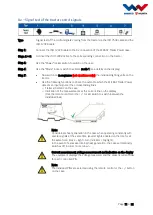
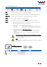
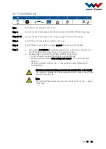
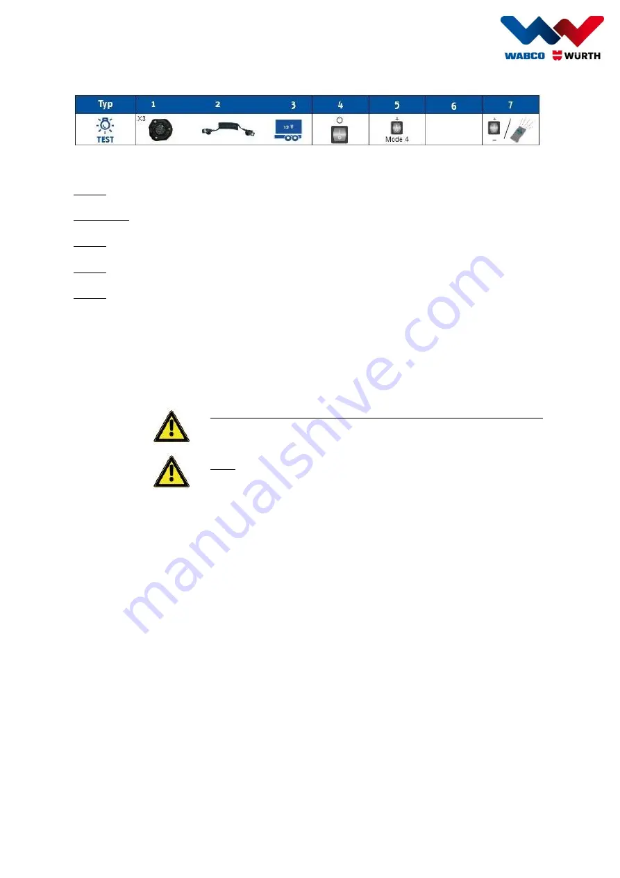
X3 – Trailer lighting test 


Type: 

Test of the trailer lighting via ISO 11446 

Step 1: 

Connect the ISO 11446 cable to the X3 connection of the W.EASY Trailer Power case. 


Steps 2 + 3: 

Connect the ISO 11446 cable to the corresponding connection on the trailer. 


Step 4: 

Use the "Power" rocker switch to switch on the case. 


Step 6: 

Use the "Mode" rocker switch to activate mode 4 (see details on the display). 


Step 7: 


Now activate in sequence the individual lighting units on the trailer and check the 

"visual" result as well as using the case to check for accuracy. 


Available aids for checking the lighting in W.EASY Trailer Power: 

o


Trailer schematic showing the currently controlled lighting 

o


Measurement and display of the voltage and current at the current line (see 
display) 

 Use the remote control or the +/- rocker switch to switch between the 

individual lines 


Current measurement, voltage measurement and indication on the display 

The equipment displays the voltage measured and the present current flow 

for each controlled PIN. 


Note: 

The individual PINs are selected using the remote control or the +/- button 

on the case. 


Summary of Contents for W.EASY Trailer Power

Page 1: ...Page 1 of 21 W EASY Trailer Power Rev 2 0 Manual Version 03 07 2018...

Page 2: ...signals 7 X2 Trailer lighting test 9 X2 Signal test of the tractor control signals 11 X2 Pin test of pins 10 12 13 X1 X2 Power supply trailer lighting test 14 X1 X2 Signal test of the tractor control...

Page 3: ...tructions Note It is forbidden to modify the equipment or to produce auxiliary equipment Such modifications can cause personal injury and malfunctions Only trained authorised persons are permitted to...

Page 4: ...tion 12V system Test of the control signals for the trailer lighting coming from the tractor via the 15 pin ISO 12098 connection 24V system Control of PINs 10 11 and 12 of the ISO 12098 connection as...

Page 5: ...tion AM Transmission channels 4 Range Up to 100 m Operating voltage 12V alkali battery type 23A Current consumption Typ 20 mA transmission Battery Nominal voltage 2 x 12V 24V Charge time 8 24 hrs depe...

Page 6: ...earth Available modes Mode Name of mode Function System type 0 Standby Detection of connected cable 1 Truck Test Signal test X1 24V Signal test X2 24V 2 Light Test Power Modulator Power X1 24V Light T...

Page 7: ...display to X1 1 Permanent positive terminal 30 X1 2 Ignition terminal 15 X1 Signal test of the tractor control signals Type Signal test of the control signals coming from the tractor via the ISO 7638...

Page 8: ...s the voltage measured from the vehicle for each controlled PIN Note The individual PINs are selected using the remote control or the button on the case Switching sequence Sequence PIN Meaning 1 X1 1...

Page 9: ...esult as well as using the case to check for accuracy Available aids for checking the lighting in W EASY Trailer Power o Trailer schematic showing the currently controlled lighting o Measurement and d...

Page 10: ...Page 10 of 21 3 X2 2 Right turn indicator 4 X2 5 Left parking light 5 X2 6 Right parking light 6 X2 8 Reversing light 7 X2 3 Fog light...

Page 11: ...hich the W EASY Trailer Power detects an input signal at the corresponding lines o Trailer schematic on the case o Indication of the measurements at the current line on the display Use the remote cont...

Page 12: ...Switching sequence Sequence PIN Meaning Icon 1 X2 7 Brake light 2 X2 1 Left turn indicator 3 X2 2 Right turn indicator 4 X2 5 Left parking light 5 X2 6 Right parking light 6 X2 8 Reversing light 7 X2...

Page 13: ...d PIN with the required signal o 24V level Rocker switch on case up button on remote control o 0V earth Rocker switch on case down button on remote control Available aids for checking in W EASY Traile...

Page 14: ...the trailer via ISO 7638 and simultaneous trailer lighting test via ISO 12098 Operation with X1 and X2 connected is as per the descriptions in the previous section for the individual modes Light test...

Page 15: ...Sequence PIN Meaning Icon 1 X2 7 Brake light 2 X2 1 Left turn indicator 3 X2 2 Right turn indicator 4 X2 5 Left parking light 5 X2 6 Right parking light 6 X2 8 Reversing light 7 X2 3 Fog light 8 X1 1...

Page 16: ...e control signals coming from the tractor via the ISO 7638 cable and the ISO 12098 cable Operation with X1 and X2 connected is as per the descriptions in the previous section for the individual modes...

Page 17: ...g sequence Sequence PIN Meaning Icon 1 X2 7 Brake light 2 X2 1 Left turn indicator 3 X2 2 Right turn indicator 4 X2 5 Left parking light 5 X2 6 Right parking light 6 X2 8 Reversing light 7 X2 3 Fog li...

Page 18: ...ng units on the trailer and check the visual result as well as using the case to check for accuracy Available aids for checking the lighting in W EASY Trailer Power o Trailer schematic showing the cur...

Page 19: ...N Meaning Icon 1 X3 6 Brake light 2 X3 1 Left turn indicator 3 X3 4 Right turn indicator 4 X3 7 Left parking light 5 X3 5 Right parking light 6 X3 8 Reversing light 7 X3 2 Fog light 8 X3 9 Permanent p...

Page 20: ...on all hardware components as standard A voluntary warranty of 6 months is given for the batteries of the W EASY Trailer Power case WABCOW RTH does not give a warranty for damage caused by external i...

Page 21: ...f equipment Power supply case Name of equipment W EASY Trailer Power Product number wa0 55 0000 1 Positive compliance by T V S D Product Service GMBH confirmed for CE approval EN 61010 This declaratio...

Reviews: