14
4
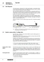
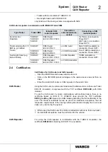
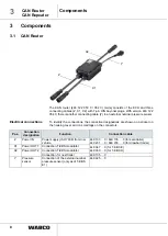
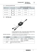
CAN Router
CAN Repeater
Workshop instructions
CAN router in
combination with Trailer
EBS
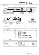
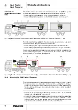
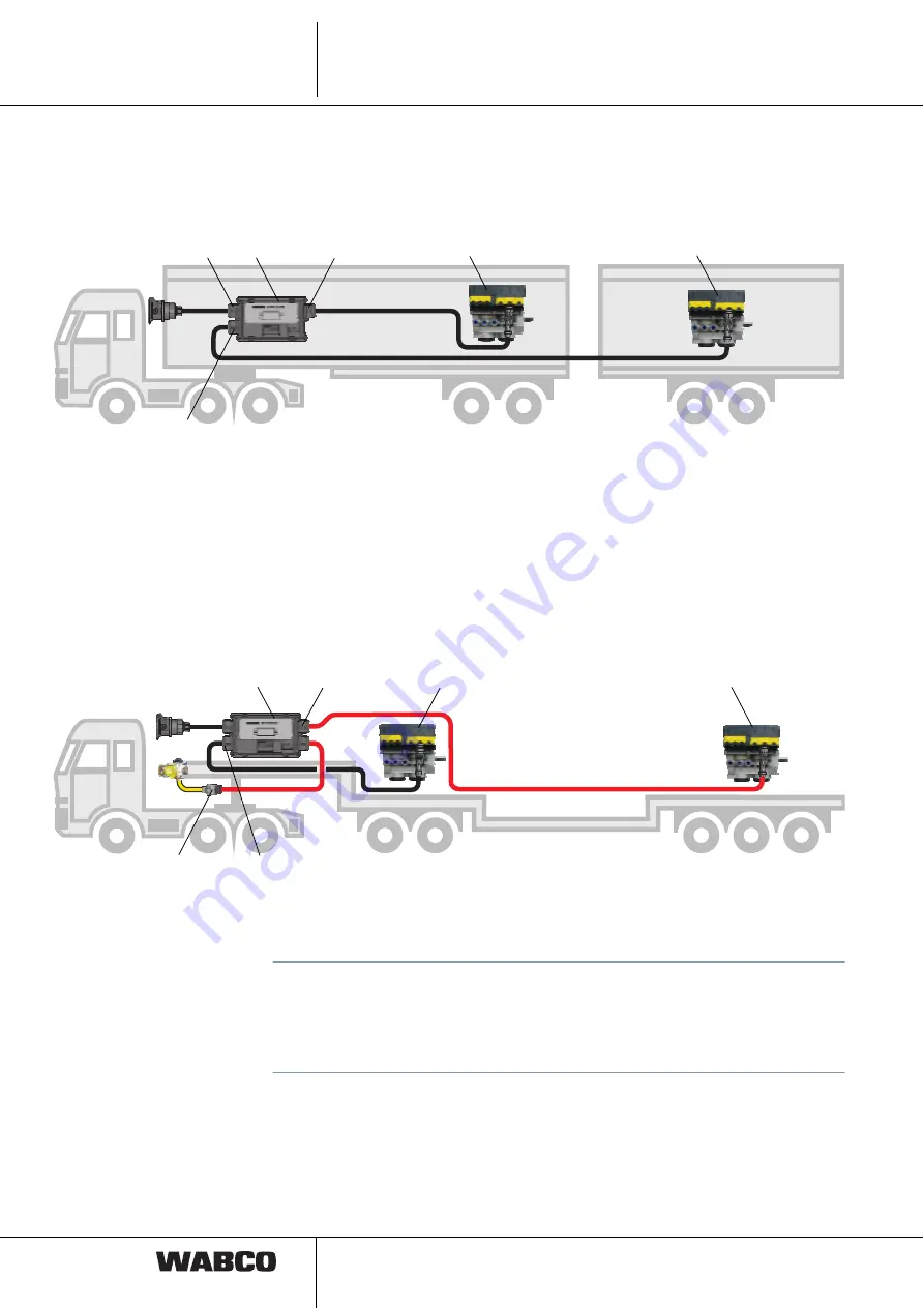
If the CAN router is used in Eurocombis or Roadtrains, make sure that the sequence
for connected T-EBS modulators is identical with the sequence of trailers.
• Power OUT1 (X1): Connection of the 1st T-EBS modulator / 1st trailer (2.1)
• Power OUT2 (X2): Connection of the 2nd T-EBS modulator / 2nd trailer (2.2)
Fig.
Using the CAN router (1) in a "Eurocombi" tractor-trailer combination with two Trailer EBS modulators (2.1, 2.2)
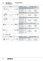
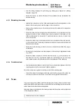
The CAN signal that is generated by the external pressure sensor is only passed on
via the Power OUT1 (X1) connection of the CAN router:
• Power OUT1 (X1): Passing on the CAN signal from external pressure sensor
• Power OUT2 (X2): Not passing on the CAN signal from external pressure sensor
Therefore, when using the CAN router in a trailer with two T-EBS E1 modulators, the
rear modulator (2.1) is always to be connected to the Power OUT1 (X1) connection
of the CAN router (1) to achieve optimal timing.
Fig.
Using the CAN router (1) with external pressure sensor (3) in a Flat Bed Trailer with two Trailer EBS E1 modulators (2.1, 2.2)
4.1.2 Mounting the CAN Router / Repeater
!
Remove the POWER plug of the Trailer EBS modulator for welding work. Position
the ground connection of the welder directly next to the welding location. Always
position the ground connection for the welder directly in the vicinity of the welding
location, to prevent magnetic fields and current flow via cables or components of
the Trailer EBS.
– Disconnect the power supply to the towing vehicle. Consider any short-circuit
hazards from batteries in the towing vehicle.
– Position the device to be accessible on the vehicle frame so that changing a fuse
is possible. The installation location of the device should be parallel to the cable
route to prevent unnecessary bending radii in the connecting cable. The CAN
repeater should be mounted in the front or on the side of the trailer.
1
X2
X1
2.1
2.2
Z
1
X2
X1
2.2
2.1
3
1


