15
4
CAN Router
CAN Repeater
Workshop instructions
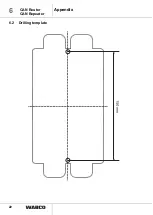
– Use the drilling template for performing any drilling (see chapter 6.2 „Drilling
template“, page 22).
– Fasten the device on vehicle frames with two suitable screws and tighten the
screws securely.
4.1.3 Mounting the cable
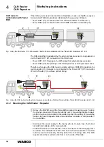
– Identify the connections on the CAN router/repeater via the designations on the
labels on the housing cover and the tags on the connections.
– Remove the protective cap on the cable and connect the cable to the respective
connections.
– Press the cable into the slot applying a little initial force. All connections must be
assigned a cable or have a closing cap. A cap is provided in the delivery of the
CAN router/repeater for connection Y (external pressure sensor), in case it will
not be connected.
– Fasten the cable only on solid elements that are connected with the components,
e.g. the vehicle frame. Fastening to flexible elements can cause cable breaks and
the seal can be broken.
– Fasten the cable and plug so that no tension or lateral forces affect the plug-in
connections.
– Be sure not to route cables over sharp edges or in the vicinity of aggressive media
(e.g. acids).
– Fasten the cable a maximum of 30 cm after the device, e.g. with a cable tie. Fix
the cable ties in such a way that the cables are not damaged (if you are using
tools, please observe the instructions of the manufacturer of the cable tie).
4.1.4 Functional test
– Use the diagnostic software to test for fault-free communication between the CAN
router/repeater and the connected T-EBS modulators.
No further steps are required for starting up the CAN router/repeater.
– Check the cables for damages and make sure that the plug and the cable are
correctly connected on the device connections during general maintenance.
4.2
Fuses
The power supply lines (PIN 1 and PIN 3) between the towing vehicle and the Trailer
EBS in accordance with ISO 7638 are protected from overvoltage and short-circuits
with 4 fuses inside the CAN router/repeater.
Defective fuses are indicated in the towing vehicle with the yellow warning light and
in the diagnostic software.
!
Defective fuses must be replaced.


