background image

15

Operation

6  Operation

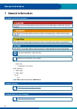
CAUTION

Risk of crushing fingers/hands


When operating the OptiFlow

TM

 Tail system there is a risk of crushing your fingers/hands.


When folding out the side panels, make sure that your fingers/hands do not get crushed.

NOTICE

Damage to the OptiFlow

TM

 Tail system

The system could be damaged if your open the portal doors while the OptiFlow

TM

 Tail system is 

folded out.


Always fold in the panels of the system before you open the portal doors.

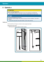
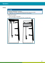
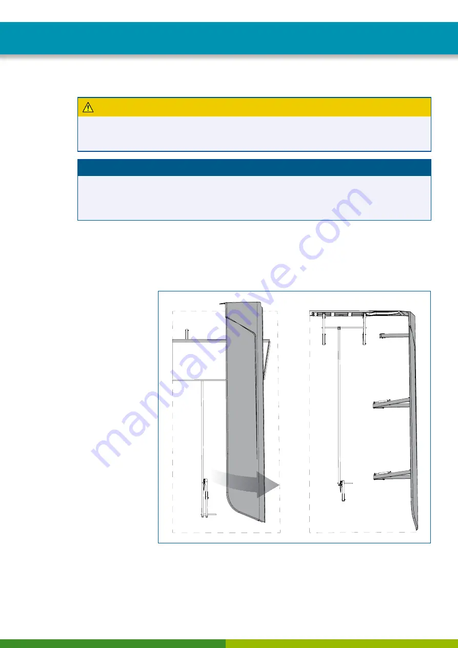
Folding out

When the OptiFlow

TM

 Tail system is folded, the Tail is deployed as follows:

Deploying the side panels


– Manually pull the side panel 

(2)

 from inside to outside.

Summary of Contents for OptiFlow Tail

Page 1: ...INSTALLATION MANUAL...

Page 2: ......

Page 3: ...n 6 4 Requirements 7 5 Installation 8 5 1 Safety information 8 5 2 Work steps 8 5 3 Final checks 13 6 Operation 15 7 Maintenance 19 8 Spare parts 20 Edition 1 10 2018 815 010 221 3 en This publication...

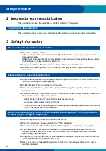
Page 4: ...escription of a possible situation which may result in irreversible injury if the warning is ignored NOTICE Description of a possible situation which may result in material damage if the warning is ig...

Page 5: ...no Italy T 39 011 4010 411 WABCO Technical Office Sales Office Training Centre Siedlecka 3 93 138 d Poland Tel 48 42 680914 WABCO Espa a S L U Av de Castilla 33 San Fernando de Henares Madrid 28830 Sp...

Page 6: ...ment if required protective goggles respiratory protection ear protectors etc Pedal actuations can lead to severe injuries if persons are in the vicinity of the vehicle Make sure that pedals cannot be...

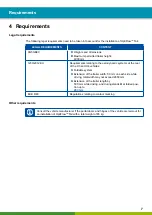
Page 7: ...mic systems at the rear of the O3 and O4 vehicles Foldable system Extension of the trailer width 50 mm on each side while driving total width may not exceed 2650 mm Extension of the trailer length by...

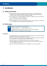
Page 8: ...s OptiFlowTM Tail consists of 2x 3 subassemblies 9 Installation tolerances 3 mm at a temperature of 18 C Install OptiFlowTM Tail in a windless environment Indoors where appropriate OptiFlowTM Tail mus...

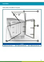
Page 9: ...9 Installation Subassemblies of the OptiFlowTM Tail system 1 2 3 LEGEND 1 Top panel left right 2 Side panel left right 3 Lifting rods left right...

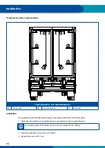
Page 10: ...Levers 2x B Gas spring 4x C Fork 2x Installation The assembly steps described below apply to the right and left side of the portal doors 1 Mark the drill positions on the portal doors in accordance wi...

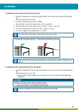
Page 11: ...any gap between trailer and sealing lip of the top panels 2 Correct position of the top panel side view Incorrect position of the top panel side view Make sure that the general trailer dimensions are...

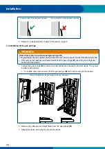
Page 12: ...handled incorrectly Only remove the cable ties and metal holder from the gas springs B once the gas springs are secured in their holders 1 Connect the gas springs B at the central and bottom door brac...

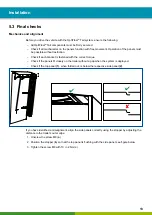
Page 13: ...ck if each bracket is fastened with the correct torque Check if the panels fit closely on the trailer without a gap when the system is deployed Check if the top panel 1 when folded out is below the re...

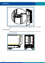
Page 14: ...dimensions of your vehicle comply with legal regulations chapter 4 Requirements page 7 Contour marking Check the contour marking according to ECE R 48 chapter 4 Requirements page 7 and correct this if...

Page 15: ...hands do not get crushed NOTICE Damage to the OptiFlowTM Tail system The system could be damaged if your open the portal doors while the OptiFlowTM Tail system is folded out Always fold in the panels...

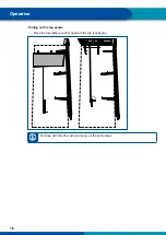
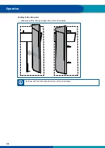
Page 16: ...16 Operation Folding out the top panels Move the lever A up until it snaps into the clip see figure Click Continue with the other side and carry out the same steps...

Page 17: ...OptiFlowTM Tail system can be damaged if you first fold in the side panels 2 Always fold in the top panels 1 first and then the side panels 2 Folding in the top panel 1 Pull the lever A out of the hol...

Page 18: ...18 Operation Folding in the side panel Manually pull the side panel 2 to the centre of the trailer Continue with the other side and carry out the same steps...

Page 19: ...A does not engage correctly the clip lock may need to be replaced chapter 8 Spare parts page 20 Check if the position of the lifting rods 3 is vertical and the connected crossbar to the top panel 1 is...

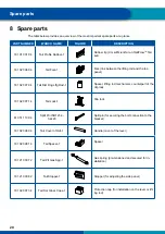
Page 20: ...Lftg Rod 1 Spacer lifting rod mechanism counterpart of the clip lock 181 020 071 4 Tail Lock 1 Clip lock 810 511 109 4 Split Pin ISO1234 3 2x20 Split pin for securing the bolt connection to the brack...

Page 21: ...21 Spare parts...

Page 22: ...Notes 22...

Page 23: ......

Page 24: ...WABCO reported sales of 3 3 billion and has nearly 15 000 employees in 40 countries For more information visit www wabco auto com About WABCO WABCO NYSE WBC is a leading global supplier of technologie...

Reviews: