background image

30

Appendix II

7.2.1 

Strain Relief at the ECU — Bracket Mounting

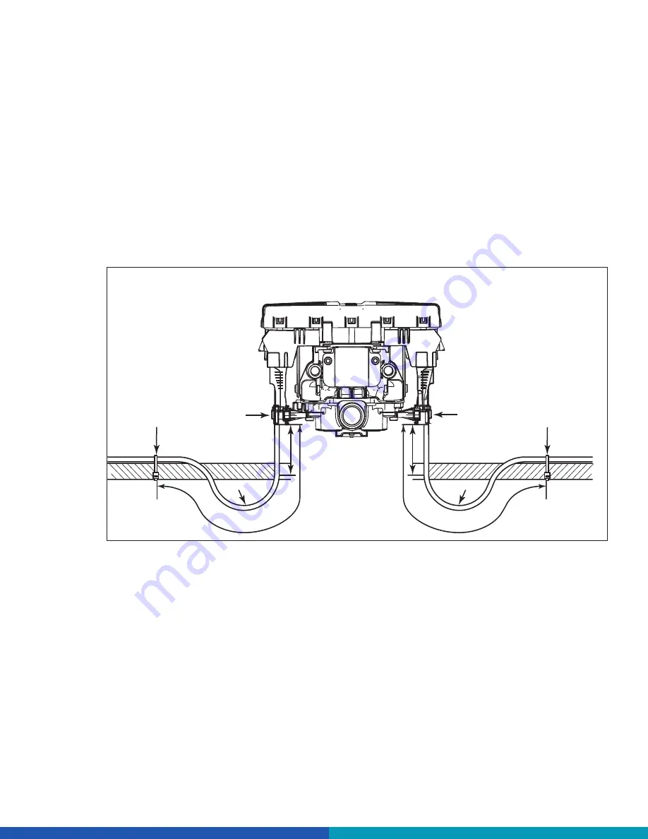
WABCO recommends that cable connections to a component, such as an ECU valve assembly, display 

a visible amount of slack in the cable up to the first tie or clip that secures the cable to the trailer structure 

or air line. This first anchor point should be a minimum 6-inches (152 mm) of cable length from the cable/

component connection and maximum of 12-inches (305 mm). This applies to all sensor, power, valve and 

GIO cables. Regardless of whether zip ties or cable clips are used, cables should be secured at intervals 

not greater than 18-inches (457 mm) to avoid cable vibration.

Ideally, cables should be affixed to the rigid structure of the trailer. A good rule of thumb is to have the bend 

of the cable, also known as bend radius, be greater than or equal to ten times the diameter of the cable. If 

the cable is 1/4-inch (6.35 mm) in diameter, then the bend should be a minimum of 2-1/2-inches (64 mm). 

Refer to figure for the ECU mounting of 2S/1M ABS.


4"

Max.

12"

R

4"

Max.

12"

10 x D

R

FASTENER

FASTENER

ZIP TIE

ZIP TIE

Bend radius (R) equal to

or greater than 10 times

cable diameter (D).

10 x D

First fastener must be

a minimum 6 inches (152 mm)

and a maximum of 12-inches

(305 mm) from connector. 

BRACKET MOUNTING - ECU REAR VIEW

4017108a


                                                                        ABS 2S/1M

Summary of Contents for TRAILER iABS 1M PREMIUM

Page 1: ...INSTALLATION INSTRUCTIONS TP18007 TRAILER iABS 2S 1M STANDARD AND PREMIUM ...

Page 2: ......

Page 3: ... 4 Preparation 10 5 Installation 12 5 1 Install the ECU Single Modulator Valve Assembly 12 5 2 Connect the Air Lines 13 5 3 Install the Two Sensor Extension Cables ABS Prepped Axles 14 5 4 Install the Power or Power Diagnostic Cable 16 5 5 End of Line Testing 20 5 6 End of Line Test with TOOLBOX PLUS Software 22 5 7 End of Line Test without TOOLBOX PLUS Software 25 6 Appendix I 27 6 1 Installing S...

Page 4: ... was in effect at the time the publication was approved for printing and is subject to change without notice or liability ZF CV Systems North America LLC reserves the right to revise the information presented or to discontinue the production of parts described at any time You will find the current edition at https zf com cvliterature ...

Page 5: ...ored CAUTION Description of a possible situation which may result in irreversible injury if the warning is ignored NOTICE Description of a possible situation which may result in material damage if the warning is ignored Important information notices and or tips Reference to information on the Internet Descriptive text Action step 1 Action step 1 in ascending order 2 Action step 2 in ascending orde...

Page 6: ...ighway Traffic Safety Administration NHTSA website to find all current documents referenced in the manual at www nhtsa gov 1 3 How to Obtain Parts and Kits Contact the WABCO Customer Care Center at 855 228 3203 United States and Canada 800 953 0248 Mexico Email wabconacustomercare zf com 1 4 WABCO TOOLBOX PLUS Software TOOLBOX PLUS Software provides PC diagnostic for WABCO products and can be purc...

Page 7: ... General Information 1 7 Your Direct Contact to ZF CVS ZF CV Systems North America LLC 1220 Pacific Drive Auburn Hills MI 48326 Customer Care Center 855 228 3203 www zf com cv wabconacustomercare zf com ...

Page 8: ... damage to components or both WARNING To prevent serious eye injury always wear safe eye protection when you perform vehicle maintenance or service WARNING Park the vehicle on a level surface Block the wheels to prevent the vehicle from moving Support the vehicle with safety stands Do not work under a vehicle supported only by jacks Jacks can slip or fall over Serious personal injury and damage to...

Page 9: ...h PLC and CAN 2S 1M Basic 2S 2M 4S 2M and 4S 3M Premium Use only genuine WABCO components Other manufacturers parts are not designed for use with a WABCO ABS system and may not function correctly WABCO recommends that a control line filter part number 432 500 005 0 be installed on the air system s control line upstream of the ABS ECU valve assembly ...

Page 10: ...ts Pipe plug 3 4 inch NPT Schedule 80 hex pipe nipple 3 4 inch NPT for air tank mounts or two Grade 8 bolts 3 8 inch and prevailing torque nuts for frame mounts SAE standard DOT approved sealing paste To ensure correct lamp operation use an incandescent type DOT approved lamp or an LED with integral load resistor WABCO components End of line testing must be done after all installations WABCO recom...

Page 11: ...PPLY PORT DELIVERY PORTS 4014010b 1M STANDARD 1M PREMIUM POWER SUPPLY ABS SENSOR D ABS SENSOR C DELIVERY PORTS DELIVERY PORTS SUPPLY PORT SUPPLY PORT EXHAUST PORT CONTROL PORT DELIVERY PORTS DELIVERY PORTS CONTROL PORT SUPPLY PORT EXHAUST PORT SUPPLY PORT 4014009b 1M STANDARD 1M PREMIUM ...

Page 12: ...e unused supply port Port 1 Apply SAE standard DOT approved sealing paste to either the first few threads or over the whole length Pipes with pre applied thread sealant may also be used 7 Rotate and tighten the ECU single modulator valve assembly a minimum of 3 turns and verify the exhaust port faces DOWN and the connection is secure Use a torque wrench on the 3 4 inch pipe plug installed on the f...

Page 13: ...en the two holes O D must be 3 25 32 inches 96 mm and mount directly to the cross member OR Build a mounting bracket with two 3 8 inch mounting holes spaced 3 25 32 inches 96 mm O D apart 4014001b TEMPLATE PLUG UNUSED PORT Exhaust port must face DOWN 3 13 16 4014006a 3 Use two 3 8 inch Grade 8 bolts with prevailing torque nuts and washers to attach the assembly to the vehicle cross member Tighten ...

Page 14: ...4 3 8 inch NPT 4 Plug any unused delivery ports 5 3 Install the Two Sensor Extension Cables ABS Prepped Axles Instructions for installing sensors on non ABS prepped axles are included in Appendix I WABCO recommends placing sensors on the axle that will provide the most braking performance The suspension manufacturer can provide this information 1 Visually inspect the tooth wheel and sensor to ensu...

Page 15: ...the cables every 8 inches 203 mm with tie wraps or cable clips 5 Plug the sensor extension cables into the ECU dual modulator valve assembly To secure push the sensor extension connection in until the locking tab seats Connect the curbside sensor at C Connect the roadside sensor at D SENSOR CABLE C SENSOR CABLE D C D SENSOR CABLE C SENSOR CABLE D D C 4013999s 1M STANDARD 1M PREMIUM 6 To provide pr...

Page 16: ...ther pack cables route the cable from the harness connector to the ECU single modulator valve assembly and secure it to prevent damage For a blunt cut power cable route the cable from the ECU single modulator valve assembly to a junction box which interfaces with the seven way connector at the front of the trailer Leave enough slack in the cable to compensate for flexing of the trailer and sub fra...

Page 17: ...g of the trailer and sub frame E Bundle any excess cable in a loop bow tie and secure the cable in the sub frame 9 Install the ABS indicator lamp on the trailer Refer to the vehicle specification sheet for the exact location of the indicator lamp Use a DOT approved lamp with ABS etched on the lens available from major trailer parts suppliers If you are using the industry standard connector cable a...

Page 18: ...ONT OF TRAILER NOTE Spring brake lines not shown SERVICE CONTROL LINES SENSOR CABLES SERVICE BRAKE SUPPLY AIR SERVICE CONTROL LINES SENSOR CABLES SERVICE BRAKE SUPPLY AIR 4014005x FRONT OF TRAILER C D 2S 1M PREMIUM VALVE MOUNTED WITH CONTROL PORT FACING REAR OF TRAILER SIDE TO SIDE CONTROL NOTE Spring brake lines not shown ...

Page 19: ...RAILER SIDE TO SIDE CONTROL FRONT OF TRAILER NOTE Spring brake lines not shown SERVICE CONTROL LINES SENSOR CABLES SERVICE BRAKE SUPPLY AIR 4014005z FRONT OF TRAILER C D 2S 1M PREMIUM VALVE MOUNTED WITH CONTROL PORT FACING REAR OF TRAILER SIDE TO SIDE CONTROL NOTE Spring brake lines not shown ...

Page 20: ...ure Using TOOLBOX PLUS Software 1 Connect a PLC diagnostic adapter to the PC USB port then connect the other end of the diagnostic adapter to the Trailer main power line J560 connection Note a list of diagnostic adapters supported by the TOOLBOX PLUS Software can be found in the Owners Manual OM1618 Refer to the Software Owner s Manual OM1618 for instructions for running TOOLBOX PLUS Software 2 Op...

Page 21: ...eld 4017037b 4017033a 4 Check the Faults field on the Main Screen NONE No faults present proceed with end of line test YES Faults present double click on YES to bring up the Fault Information Screen You may also select the Display menu at the top and then click on Faults to bring up the Fault Information Screen Use the information in the Repair Instructions field to perform the necessary repairs ...

Page 22: ...ct Valves Lamp to display the Valve Activation Screen The H1 valve indicator will be selected 4017038a 5 Click on the Activate button and listen for the valve to click indicating a good installation The Test Status box at the bottom of the menu will also display the status of this test 6 Click on the Test button to activate the ABS indicator lamp this is the lamp that is mounted on the side of the...

Page 23: ...entation test 1 Raise the sensed wheel ends off the ground 2 Apply air to the emergency supply line to fill the air tanks and release the spring brakes so that the wheels can be rotated 3 Apply 12 volts DC to the ABS 4 At the Trailer Main Menu click on Component Test then select Sensor Orientation Test to display the Sensor Orientation Test screen When the Sensor Orientation Test screen first appe...

Page 24: ... mounting orientation of the ECU single modulator valve assembly Refer to the following illustrations for the ECU mounted with sensors facing forward and rear The correct mounting orientation must be selected prior to starting the test 4017035a 6 Click on Start to begin the test 4017036a ...

Page 25: ...enter at 855 228 3203 Sensor output appears in the Sensors field located in the bottom right portion of the Sensor Orientation Test screen 5 7 End of Line Test without TOOLBOX PLUS Software 1 Apply 12 volts DC power to the ABS 2 The ECU single modulator valve assembly should click two times 3 If the indicator lamp comes on for three seconds and goes out This indicates a correct installation The en...

Page 26: ...the correct location 4005501a If the ABS indicator lamp comes on and stays on when you apply the brakes to a moving vehicle the trailer ABS is not working properly The ABS must be serviced as soon as possible upon completion of your trip to ensure full anti lock braking capability TP 95172 Rev 4 98 NOTICE If this label is not included with the assembly let your supervisor know Labels are available...

Page 27: ...ng clip as far as possible Use WABCO spring clips to ensure a correct fit 3 Push the spring clip into the sensor holder from the inboard side until the spring clip tabs are against the sensor holder Push the sensor into the spring clip as far as possible SPRING CLIP TAB SENSOR SPRING CLIP SENSOR HOLDER 4003572a 4 Route the sensor cable toward the brake chamber over the brake spider or through the ...

Page 28: ...heel pushes against the sensor as the wheel bearings are adjusted There should be no gap between the sensor and the tooth wheel 6 Test the sensor output voltage Use a volt ohm meter to check the output voltage of the sensors while rotating the wheel at approximately 1 2 revolution per second Minimum output must be 0 2 volt AC If minimum output is less than 0 2 volt AC push the sensor toward the to...

Page 29: ...isture could intrude Unnecessary wear at bend points can be the result of a cable under tension Cable strain relief is a universal practice It applies to all WABCO product lines from Anti Lock Brake Systems ABS to Roll Stability Systems RSS 7 2 Excess Cable Length In cases where the length of cable exceeds what is required the excess must be bundled in an efficient manner It should not be draped o...

Page 30: ...es should be secured at intervals not greater than 18 inches 457 mm to avoid cable vibration Ideally cables should be affixed to the rigid structure of the trailer A good rule of thumb is to have the bend of the cable also known as bend radius be greater than or equal to ten times the diameter of the cable If the cable is 1 4 inch 6 35 mm in diameter then the bend should be a minimum of 2 1 2 inch...

Page 31: ...reater than 18 inches 457 mm to avoid cable vibration Ideally cables should be affixed to the rigid structure of the trailer However structure is not always available on tank mounted installations In these cases securing the cable may be accomplished by fastening the cable to nearby air lines It is important to note that cables should be secured only to the extent that the cable is held sufficient...

Page 32: ...fastened in a manner where the cable is secured enough where the cable will not move or chafe against what it is mounted to A small amount of slack should be present to ensure that the cables do not become taut after installation or the servicing of components The figure illustrates the correct amount of slack in the sensor extension cables and correct attachment to the air delivery lines for ABS ...

Page 33: ...s must be placed between 2 and 4 inches 51 102 mm from the cable connector to ensure correct strain relief Regardless of whether zip ties or cable clips are used cables should be secured at intervals not greater than 18 inches 457 mm to avoid cable vibration 4012336a 3 76 MM 3 76 MM ZIPTIES ON AIR LINES 4011417a 3 76 MM SENSOR CABLE ZIPTIES ON AXLE ...

Page 34: ... such as axles should also be electrically connected to the common chassis ground If the axles are not correctly grounded to the chassis a ground strap electrically connecting the axle to the chassis may be added to ensure adequate protection from unwanted electrical noise This can be verified by measuring the resistance between the vehicle chassis frame and the other trailer component then confir...

Page 35: ...IV 9 1 Parts and Variant List VARIANT LIST Variants System Configuration 2S 1M Standard 2S 1M Premium Part Number 400 500 320 0 400 500 350 0 CAN Capable Yes Yes GIO Capable No Yes Direction of Control Side to Side Side to Side ...

Page 36: ... F 4019730a Sensor Extension Cable 449 733 008 0 449 733 013 0 449 733 018 0 449 733 030 0 449 733 050 0 449 733 070 0 449 733 090 0 449 733 120 0 0 8 M 1 3 M 1 8 M 3 M 5 M 7 M 9 M 12 M Modulator 4019731a GIO Cable 3 Pin 3rd Mod 449 407 030 0 449 407 060 0 449 407 080 0 449 407 120 0 3 M 6 M 8 M 12 M GIO 1 or 2 4019732a GIO Cable 3 Pin 449 826 010 0 449 826 030 0 449 826 100 0 1 M 3 M 10 M GIO 1 o...

Page 37: ... 030 0 1 M 3 M Subsystem 4019737a Subsystem Cable OptiLink IVTM Trailer CAST 449 928 050 0 449 943 050 0 449 928 120 0 449 943 120 0 5 M 5 M 12 M 12 M Subsystem 4019738a Subsystem Cable Smartboard II 449 929 040 0 449 929 060 0 449 929 120 0 4 M 6 M 12 M Subsystem 4019739a HUB Cable Subsystem 894 600 161 2 0 5 M Power 4019740a HUB Cable Power 1M Only 894 600 151 2 0 5 M GIO 1 or 2 4019741a HUB Cab...

Page 38: ...on serves the full commercial vehicle industry value chain As the automotive industry progresses towards an increasingly autonomous connected and electrified ACE future ZF s CVS division innovates integrates and supplies components and advanced control systems that help make commercial vehicles and fleets operate more safely and sustainably CVS unites ZF s former Commercial Vehicle Technology and ...

Reviews: