62
16. 2-axis coordinate tables K400 and K600
16.1 Assembly
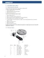
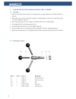
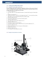
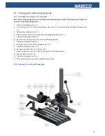
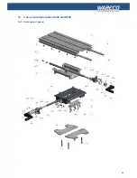
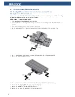
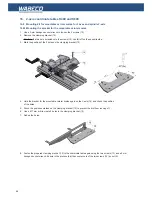
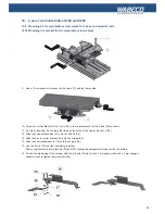
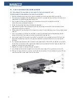
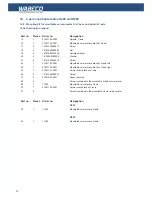
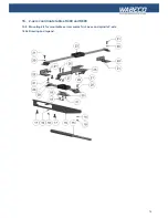
1. Screw on the crank handles (4.4) and (5.4) the respectively handwheel.
2. Fix the milling table with the base plate of the drilling milling stand using 4 screws M10.
16.2 Lubrication
Proper care and maintenance are essential for a long service life. All sliding surfaces and feed screws must be thoroughly
oiled with customary greasing oil before each use.
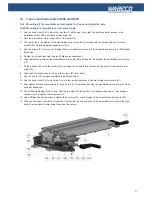
To do so, the top slide (1) must be moved in the respective axes back and forth during the lubrication procedure.
16.3 Re-adjust the guides
To re-adjust the guides please proceed as follows:
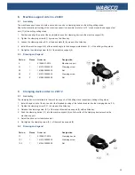
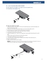
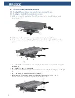
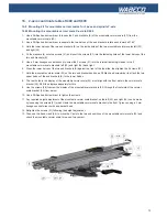
1. Loosen the counter nut (9.1) respectively (10.1)
2. Adjust the two taper gibs (7) and (8) with the eccentric setscrews (9) and (10) so that each axis can be traversed
without play and with little effort. The corresponding carriage should proceed repeatedly during the adjustment and
should be checked for play and function.
3. Retighten the counter nut (9.1) respectively (10.1)
Fix the eccentric setscrews (9) and (10) only if the associated taper gib lies flat in the area of the respective ec
-
centric setscrew on the counter guide! Otherwise it may cause jamming of the guidance and may be damaged.
16.4 Working instructions
Metal and plastic and wooden work pieces are clamped with a vice or clamping jaws.
The travel path of the milling table can be read off within 1/10 mm on 2 adjustable graduated collars.
When milling always feed the work piece against the cutting direction of the tool.

