11
2.
Delivery and set up
The place of set-up should be selected in such a way that
■
there is sufficient lighting
■
the electrical supply cable with socket outlet with earthing contact and 0-conductor is installed
close enough to the machine that the supply line is not subjected to any tensile load.
The machine has to be screwed to the installation surface and/or provided with a safe stand by using
level elements. For this purpose, the base cabinet of the machine has four fixation thread bores (M10)
as well as four fixation bores (Ø 12.5 mm).
The doors of the safety cabin can only be opened if the machine is switched to operation modes CNC
or set-up if the main spindle is not moving.
2.1
Transport of machine
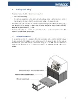
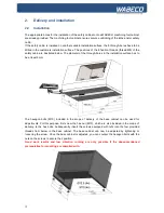
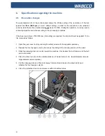
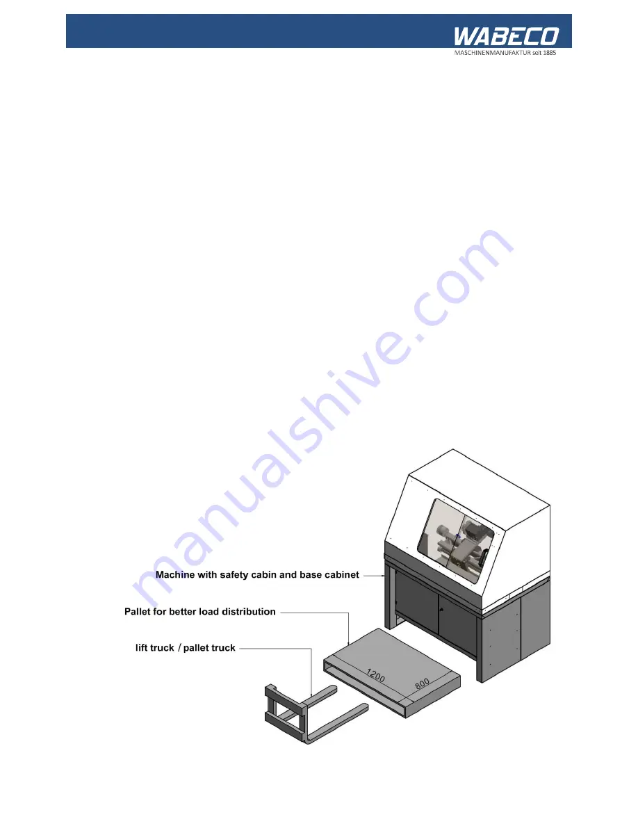
To transport the machine it is advisable to lift it at the lower cabinet with a forklift or platform trolley at
the base cupboard of the safety cabin and carefully move it to the desired location. For this purpose,
use wide forks (max. 1260 mm). We recommend using an intermediate plate for optimal load
distribution and the protection of the machine. For example, a Euro-pallet of 1200 x 800 mm is
suitable.
.
Summary of Contents for CC-D6200 hs
Page 1: ...Operating Instructions CNC lathe With slant bed CC D6200 hs ...
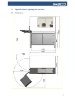
Page 17: ...17 4 Specifications regarding the machine 4 4 Dimensions ...
Page 25: ...25 8 Lubrication oft he machine ...
Page 34: ...34 16 Drawings and legends 16 1 Headstock with Motor ...
Page 36: ...36 16 Drawings and legends 16 2 Bed with lead screw ...
Page 38: ...38 16 Drawings and legends 16 3 Cross slide with saddle apron ...
Page 40: ...40 16 Drawings and legends 16 4 Tailstock ...
Page 48: ...48 16 Drawings and legends 16 10 Operating console ...
Page 52: ...52 17 Circuit diagram 17 1 Overall connection diagram see legend for circuit diagrams 17 3 ...


