30
13. 3 and 4 jaw lathe chuck
The 3-jaw lathe chuck
Is used to tension circular, three and six edged work piece centrally to the spindle axis.
The 4-jaw lathe chuck
Is used to tension square work pieces centrally to the spindle axis.
Risk of accidents
Do not attempt to clamp work pieces that are over the permitted clamping range. The
clamping force is thus too low and the jaws may come undone
The maximum revolution range specified on the lathe chuck may not be exceeded
Mounting the jaws:
1. The jaws and guides are numbered from 1 - 3 or 1
– 4.
2. Open the lathe chuck with the key in such a way that the drilling jaws are released (sequence: 3,
2, 1 or 4, 3, 2, 1)
3. Insert turning jaw 1 into guide 1
4. Push turning jaw 1 in the direction of the chuck centre point and, at the same time, turn the chuck
key clockwise
5. When the coil has caught turning jaw 1, insert turning jaw 2 into guide 2
6. Repeat the procedure with jaws 2, 3 and 4 (for a four jaw lathe chuck)
7. Then visually check the positions of the jaws. These must meet centrally
Mounting the drilling jaws:
1. If you wish to use the drilling jaws again, the process is the repeated in the same order.
2. Three jaw lathe chuck: First jaw 1, then 2, then 3
3. Four jaw lathe chuck: First jaw 1, then 2, then 3, then 4
Summary of Contents for CC-D6200 hs
Page 1: ...Operating Instructions CNC lathe With slant bed CC D6200 hs ...
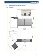
Page 17: ...17 4 Specifications regarding the machine 4 4 Dimensions ...
Page 25: ...25 8 Lubrication oft he machine ...
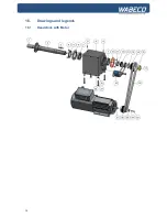
Page 34: ...34 16 Drawings and legends 16 1 Headstock with Motor ...
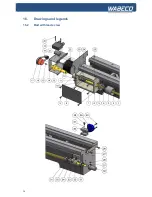
Page 36: ...36 16 Drawings and legends 16 2 Bed with lead screw ...
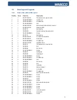
Page 38: ...38 16 Drawings and legends 16 3 Cross slide with saddle apron ...
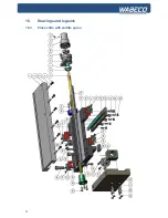
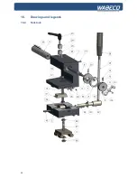
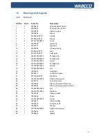
Page 40: ...40 16 Drawings and legends 16 4 Tailstock ...
Page 48: ...48 16 Drawings and legends 16 10 Operating console ...
Page 52: ...52 17 Circuit diagram 17 1 Overall connection diagram see legend for circuit diagrams 17 3 ...

