142
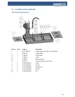
19. Coolant system (optional)
19.4 Safety regulations for the handling of cooling lubricant
1. Pay particular attention to leaked coolant as this can quickly cause people to slip and caused
accidents as a result.
2. Secure your coolant system in such a way that it cannot be switched on by children. Persons who
have not been trained may not operate the coolant system.
3. Ensure you have a clean workplace, dirty areas can quickly lead to accidents.
4. Never use the coolant system when processing magnesium alloys. In combination with water-
mixed coolants, this may result in flammable gas mixtures which may explode under certain
circumstances.
5. Avoid longer skin contact with the coolant.
6. Use skin protecting creams when handling coolants.
7. Regularly monitor the concentration of the water-mixed coolant.
8. Regularly monitor the pH value of the coolant.
9. Make sure that the coolant is only disposed of in an environmentally friendly way in accordance
with the relevant guidelines. Coolant is a special waste product.
19.5 Filling the coolant system
A number of protective measures must be observed and taken in order to ensure that the handling of
coolant does not cause health risks or environmental loads.
■
Always observe the datasheet and the safety regulations of the coolant being used (can be
obtained from the supplier or manufacturer)
■
Observe all safety regulations set out in these operating instructions, in particular those that refer
to the safe handling of coolants.
■
In order to ensure reliable operation of the coolant pump, a minimum coolant filling level is
required in the coolant tank.
■
The capacity of the coolant system is approximately 13 litres.
■
The maximum filling level should be just below the shelf insert
■
The minimum filling level is approximately 15 mm below that.
■
To fill, remove the shelf insert and fill to the maximum filling level with a suitable coolant whilst
observing all safety regulations.
■
After filling, replace the shelf insert
Summary of Contents for CC-F1200 high speed
Page 42: ...42 6 Fitting and removing the tools 1 2 3 4 5...
Page 68: ...68 17 Drawings and legends 17 2 Electronic hood with 1 4 kW motor 17 2 2 CC F1200 CC F1210...
Page 70: ...70 17 Drawings and legends 17 3 Milling head with 1 4 kW motor...
Page 72: ...72 40 1 51004008 0002 Mounting pin 17 Drawings and legends 17 4 Milling head with 2 0 kW motor...
Page 74: ...74 17 Drawings and legends 17 4 Milling head with 2 0 kW motor...
Page 76: ...76 17 Drawings and legends 17 5 Z stand with vertical skid with trapezoidal threaded spindle...
Page 82: ...82 17 7 Lateral drive for z axis with trapezoidal threaded spindle 17 Drawings and legends...
Page 84: ...84 17 8 Cross slide support with trapezoidal threaded spindle 17 Drawings and legends...
Page 94: ...94 17 Drawings and legends 17 11 Z stand with vertical skid with ball screw spindle...
Page 100: ...100 17 Drawings and legends 17 13 Lateral drive for z axis with ball screw spindle...
Page 102: ...102 17 Drawings and legends 17 14 Cross slide support with ball screw spindle...
Page 114: ...114 17 Drawings and legends 17 20 Operating console for 1 4 kW motor...
Page 116: ...116 17 Drawings and legends 17 20 Operating console for 1 4 kW motor...
Page 118: ...118 17 Drawings and legends 17 21 Operating console for 2 0 kW motor...
Page 120: ...120 17 Drawings and legends 17 21 Operating console for 2 0 kW motor...
Page 122: ...122 17 Drawings and legends 17 22 Bracket arm for operating console...
Page 124: ...124 17 Drawings and legends 17 23 Industrial monitor and folio keyboard...


