background image


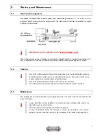
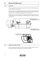
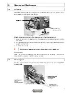
14 

7. Speed 

regulation


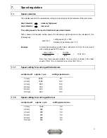
7.1.3 

Speed setting for working with Brass, Copper 


workpiece-


Ø


approx. r.p.m.. 

cutting speed m/min 

10 mm 

2300 

80 

20 mm 

1270 

80 

40 mm 

640 

80 

60 mm 

425 

80 

80 mm 

320 

80 

100 mm 

250 

80 


7.2 Speed 

change 


Rotational speed range 45 - 2300 min-1: 

The rotational speed of the work spindle is infinitely variable between 45 and 400 r.p.m. in the 1

st


step or in the 2

nd

 step between 200-2300 r.p.m using the potentiometer on the front side of the 

machine. 


speed setting at the potentiometer

1. step r.p.m. 

2. step r.p.m. 

10 45 

200 

20 105 

350 

30 175 

740 

40 260 

1050 

50 325 

1440 

60 360 

1650 

70 400 

1860 

80 460 

2120 

90 490 

2160 

100 500 

2300 


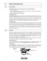
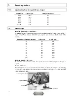
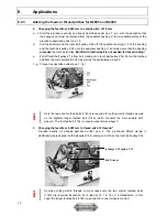
Rotational speed 45 - 400 r.p.m.: 

The drive belt must be relocated if the lower speed level with a minimum speed of 45 r.p.m. is 

required. 


Proceed as follows: 


Remove the protective cover and release the drive belt by unscrewing the clamping nut and turning 

the star handle clockwise until the drive belt can be relocated. Then re-tighten the drive belt in the 

reverse sequence of steps. 

clamping nut

star handle

potentiometer

rotational speed  45-400 rpm


Summary of Contents for D2400

Page 1: ...00 Walter Blombach GmbH Tool and Machine Factory D 42899 Remscheid Am Blaffertsberg 13 Phone 0049 2191 597 0 Fax 0049 2191 597 40 E Mail info wabeco remscheid de D 54673 Neuerburg WABECO Str 1 10 Phon...

Page 2: ...or copies of this document of any kind or of exerts require a written approval by WABECO Disposal of the lathe The transport and protective packagings are made up of the following materials corrugated...

Page 3: ...1 Longitudinal and transverse turning 15 8 2 Thread cutting with automatic feed 16 8 2 1 General note 17 8 2 2 Application of change gears 17 8 2 3 Altering the feeds or thread pitches for D2000 D2400...

Page 4: ...lare that the universal milling and drilling machines specified below Universal Lathes Typ D2000 D2400 D3000 meet the following regulation requirements for standard series production directive for mac...

Page 5: ...5 1 Machine dimensions 1 1 D2000 1 2 D2400...

Page 6: ...6 1 Machine dimensions 1 3 D3000...

Page 7: ...rements for secure mounting are observed The machine should be installed in a well lighted area and electrical cables with earthed sockets and O conductors must be installed close to the machine so th...

Page 8: ...drive closed 8 The turning tools must be tightly clamped at the correct height and as short as possible 9 The turning tools must never be replaced when the machine is running 10 Never leave the clamp...

Page 9: ...once more be cleaned with great care and all lubrication points have to be lubricated with grease Thoroughly oil the cross support lead screws guiding rods and spindle sleeve Check all spindles by ha...

Page 10: ...ell as the tailstock sleeve have to be greased with lubricating oil every 100 service hours When greasing make sure to put the slide of the cross support to its hindmost position while moving the tail...

Page 11: ...nut is located at the rear end of the work spindle 2 Turn the adjustment nut clockwise until the bearings run free of play again the work spindle can easily be turned by hand 3 Re Tighten the stud bol...

Page 12: ...the guide bars e g in face turning The screw pulls the block at the bottom of the transverse support against the two guide bars 6 8 Tailstock The tailstock is attached to the guide bars in such a way...

Page 13: ...0 mm is to be turned with a cutting speed of 100 m min Now from those speeds available the one which is closest to the ideal speed of 1592 1 min is selected in our case 1600 1 min 7 1 1 Speed setting...

Page 14: ...of the machine speed setting at the potentiometer 1 step r p m 2 step r p m 10 45 200 20 105 350 30 175 740 40 260 1050 50 325 1440 60 360 1650 70 400 1860 80 460 2120 90 490 2160 100 500 2300 Rotati...

Page 15: ...d or to the right By using them a maximum of material is removed in as short a time as possible without paying attention to the finish on the surface of the work piece They can be used for longitudina...

Page 16: ...iece centre as otherwise the profile of the thread would be distorted In order to obtain the correct position of the thread flanks to the axis of the workpiece the grinding jig is put against the work...

Page 17: ...ed system the lead screw and the lead screw drive are connected to an overload clutch 8 2 2 Application of change gears for D2000 and D2400 For the purpose of automatic longitudinal turning there are...

Page 18: ...20 120 120 120 120 120 120 120 E 140 140 140 140 140 140 140 140 140 140 Z 1 24 26 28 30 32 34 36 A 34 34 34 34 34 34 34 B 24 18 18 24 18 18 14 C 32 26 28 40 32 34 28 C1 32 32 32 32 32 32 32 D 120 120...

Page 19: ...ley E d Remove both tooth belt pulleys Z 14 from bolts A and B and replace them by toothed belt pulley Z 18 or toothed belt pulley Z 20 respectively Mount and tighten the washers and nuts to A and B e...

Page 20: ...h belt pulley Z 36 Put on the toothed belt from the main spindle to bolt A as well as the belt between A and C f g Proceed as described under pos 1 f g i Only the two short toothed belts 1145 are requ...

Page 21: ...tting inch threads this wheel has to be replaced by toothed wheel Z 34 For the different thread pitches only the tooth wheels B beside Z 48 and C on the main spindle are to be changed according to tab...

Page 22: ...kspindle loosen the adjustment nut and remove it from the main spindle f Remove the V belt pulley No 1112 the distance piece No 1113 and the toothed belt wheel No 1114 from the workspindle Mount the t...

Page 23: ...the clamping plate The tool is to be clamped as short as possible into the collet danger of breakage If the tool is firmly clamped the depth adjustment is done via the feed shaft Assembly of the angle...

Page 24: ...erve the following clean rinse the circulation system tray filter determine the concentration necessary to meet the technical demands concentrate water 1 5 1 30 check the water has a low level of nitr...

Page 25: ...ably in order to determine whether additional safety measures are necessary or not Other factors which influence the actual stress level of employees are the characteristics of the working area other...

Page 26: ...acer sleeve 1116 10201116 Tapered roller bearing 11141 10211141 Starter pulley 1114 10201114 Toothed belt pulley 1113 10201113 Spacer sleeve 1112 10101112 Belt pulley for D2000 1112 10201112 Belt pull...

Page 27: ...ud bolt radial nut 1252 10201252 Support 1253 10201253 Potentiometer for speed regulation 1254 10201254 Main switch with undervoltage release 1255 10201255 Switch right left 1256 10201256 Motor 1260 1...

Page 28: ...28 13 Drawings and list of parts 13 3 Lead screw drive for D2400 and D3000...

Page 29: ...1126 10201126 Pressure spring 1127 10201127 Coupling 1131 10201131 Eccentric shaft complete 11311 10211311 Stud bolt nut 11315 10211315 Ball bearing 114 10200114 Change gear quadrant 1141 10201141 He...

Page 30: ...30 13 Drawings and list of parts 13 4 Lead screw drive for D3000 1 2 3 4 5 7 6 21 20 19 18 17 16 15 14 13 12 11 10 9 8...

Page 31: ...s 6 10300006 Bracket 7 10300007 2 screws 8 10300008 2 adjusting nuts 9 10300009 Pressure ring 10 10300010 Bushing 11 10300011 2 thrust bearings 12 10300012 Thrust washer 13 10300013 2 screws 14 103000...

Page 32: ...32 13 Drawings and list of parts 13 5 Drive with gear transmission for D2000...

Page 33: ...1471 10111471 Washer 114114 102114114 Toothed belt pulley Z 14 11823 10111823 Toothed belt 11914 10111914 Drive belt J 610 11911 10111911 Screw with washer 1173 10101173 Retaining plate 11811 10111811...

Page 34: ...34 13 Drawings and list of parts 13 6 Cross support...

Page 35: ...ing gib 321 10200321 Lower part of longitudinal support 322 10200322 Upper part of longitudinal support 3221 10203221 Spindle bearing compl with graduated ring 32211 10232211 Spindle for longitudinal...

Page 36: ...ock 421 10200421 Spindle sleeve 422 10200422 Flange 1151 10201151 Hexagon socket screw 423 10200423 Spindle 4231 10204231 Adjusting ring 4234 10204234 Spring washer 4233 10204233 Washer 31212 10231212...

Page 37: ...asher 523 10200523 Thrust needle bearing 31212 10231212 Ball ended crank 4231 102H4231 Spacer sleeve 524 10200524 Bronze bushing 53 10200053 Protective channel 531 10200531 Screw washer 4232 10204232...

Page 38: ...38 14 Circuit diagram 14 1 For D2000 and D2400 mains plug emergency OFF main switch reversing switch switch for protection cap potentiometer Date Danger control electronics motor...

Page 39: ...D3000 potentiometer rear side capacitor rectifier transformer reversing switch main switch emergency OFF mains plug potentiometer control electronics motor feed motor control electronics reversing swi...

Reviews: