41
5.
Achieving optimum results and avoiding incorrect usage
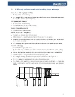
Curved lathe chisel right (2) and left (1)
■
For longitudinal and face turning
■
This is designed to remove as much material as possible in a short time (without paying attention
to the surface created on the work piece).
Offset lateral lathe chisel (3)
■
For longitudinal and face turning
■
Is used for finishing (creating a clean surface).
External thread lathe chisel (4)
■
Is used for cutting external threads
Narrow square-nose cutting tool (5)
■
Is used to cut grooves and cut off work pieces
■
Attention should be paid to the precise height of the centre of the turning steel.
■
Work with low revolutions and cool the tool (cooling via drilling oil or emulsion: acts as lubrication
and removal of shavings).
■
The cutting steel is to be tensioned as short as possible and at a right angle to the rotational axis.
Inner lathe chisel (6)
■
Is used for hollowing out drilled holes.
■
Tension as short as possible to prevent the occurrence of turning steel vibrations (untidy surface).
■
As a result of the forces exerted on the turning steel, the steel must be short and secured firmly.
■
If the lever arm is too long, the lathe chisel will bend and spring back.
■
The cutting edge will penetrate the work piece unevenly and result in a bumpy surface.
■
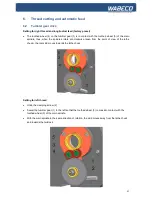
The turning steel is to be aligned with the centre of the turning element
■
The checking of the height to the centre of the work piece is carried out with the help of the turning
centre point in the tailstock. The height position of the turning steel is achieved by adding even
sheets.
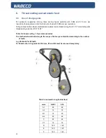
6
5
4
3
2
1
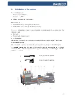
Summary of Contents for D6000
Page 76: ...76 18 Drawings and legends 18 3 Protective hood drive 2 0 kW motor...
Page 78: ...78 18 Drawings and legends 18 4 Electronic console 2 0 kW motor...
Page 86: ...86 18 Drawings and legends 18 10 Bed with lead screw with trapezoidal threaded spindle...
Page 90: ...90 18 Drawings and legends 18 11 Bed with lead screw with ball screw spindle...
Page 94: ...94 18 Drawings and legends 18 13 Tool skid Transverse skid...
Page 96: ...96 18 Drawings and legends 18 14 Tool skid Lock plate...
Page 98: ...98 18 Drawings and legends 18 15 Tool skid Longitudinal skid...
Page 100: ...100 18 Drawings and legends 18 16 Transverse skid with lock plate with ball screw spindle...
Page 102: ...102 18 Drawings and legends 18 17 Tailstock...
Page 104: ...104 18 Drawings and legends 18 18 Motor for control of the x axis...
Page 106: ...106 18 Drawings and legends 18 19 Motor for control of the z axis...
Page 108: ...108 18 Drawings and legends 18 20 Operating console for 1 4 kW motor...
Page 110: ...110 18 Drawings and legends 18 20 Operating console for 1 4 kW motor...
Page 112: ...112 18 Drawings and legends 18 21 Operating console for 2 0 kW motor...
Page 114: ...114 18 Drawings and legends 18 21 Operating console for 2 0 kW motor...
Page 116: ...116 18 Drawings and legends 18 22 Bracket arm for operating console...
Page 118: ...118 18 Drawings and legends 18 23 Industrial screen and membrane keyboard...
Page 138: ...138 19 Circuit diagram 19 9 Multiphase motor with end stop...
Page 154: ...154 23 Safety cabin optional 23 8 Drawing and legend...
Page 163: ...163 26 Tensioning bracket with milling machine table optional 26 7 Drawing and legend...


