86
10. Feed
motion
10.1
Feed motion X,Y and Z-axis
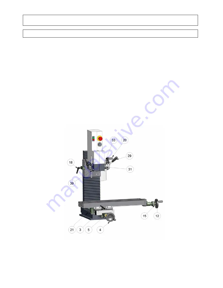
The traverse and longitudinal motion of the cross support (X,Y-axis) is accomplished by turning the
handwheels (parts-no. 4 and 12). Both slides can be blocked with the aid of clamping levers
(parts-no. 21 and 3).
The feed motion – drilling and milling depth (Z-axis) – is accomplished by using the handwheel
(part-no. 20).
To operate the milling head by means of the handwheel, loosen clamp lever (part-no. 18) and
fix it again after operation.
Graduated collars have been installed to enable the feed path to be read off (parts-no. 5, 15 and
33). One full rotation of the handwheel corresponds to 4 mm of the slide path and with ball rolling
spindle 5 mm, one graduation on the collar corresponds to 0,05 mm on the path.
Feed path of the axes:
- longitudinal
X-axis
500 mm
- transverse
Y-axis
200 mm
-
vertical
Z-axis
280
mm
Another possibility of operating the tool spindle is by turning the control lever (part-no. 29). After
loosening the clamping lever (part-no. 39) the control lever can be turned. One graduation on the
collar (part-no. 31) corresponds to 1 mm of travel.
The work spindle has a maximum travel of 55 mm. The clamping lever must be well tightened up
again afterwards.
We recommend that the travel (engagement) should not be selected too generously, but that in the
case of greater engagement depth this should be accomplished in multiple steps.
Summary of Contents for F1410 LF
Page 7: ...7...
Page 8: ...8 1 Product range 1 1 F1410 LF with trapezoid thread spindle...
Page 10: ...10 1 Product range 1 2 F1410 LF high speed with trapezoid thread spindle...
Page 12: ...12 1 Product range 1 3 F1410 LF with ball bearing spindle...
Page 14: ...14 1 Product range 1 4 F1410 LF high speed with ball bearing spindle...
Page 16: ...16 1 Product range 1 5 CC F1410 LF...
Page 18: ...18 1 Product range 1 6 CC F1410 LF high speed...
Page 22: ...22 3 Drawing and list of parts 3 1 Protective cover with electrical equipment for F1410 LF...
Page 24: ...24 3 Drawing and list of parts 3 2 Protective cover with electrical equipment for CC F1410 LF...
Page 27: ...27...
Page 28: ...28 3 Drawing and list of parts 3 4 Milling head with 1 4 kW motor for F1410 LF and CC F1410 LF...
Page 34: ...34 3 Drawing and list of parts 3 7 Base machine F1410 LF with trapezoid thread spindle...
Page 36: ...36 3 Drawing and list of parts 3 8 Base machine F1410 LF with ball bearing spindle...
Page 38: ...38 3 Drawing and list of parts 3 9 Base machine CC F1410 LF...
Page 40: ...40 3 Drawing and list of parts 3 10 Vertical slide F1410 LF with trapezoid thread spindle...
Page 42: ...42 3 Drawing and list of parts 3 11 Vertical slide F1410 LF with ball bearing spindle...
Page 44: ...44 3 Drawing and list of parts 3 12 Vertical slide CC F1410 LF...
Page 48: ...48 3 Drawing and list of parts 3 15 Top slide CC F1410 LF...
Page 57: ...57...
Page 58: ...58 3 Drawing and list of parts 3 23 Control station milling plus 1 4 kW...
Page 60: ...60 3 Drawing and list of parts 3 24 Control station milling plus 2 0 kW...
Page 62: ...62 3 Drawing and list of parts 3 25 Control station nccad 1 4 kW...
Page 64: ...64 3 Drawing and list of parts 3 26 Control station nccad 2 0 kW...
Page 66: ...66 3 Drawing and list of parts 3 27 Mounting for linear measuring scales...


