146
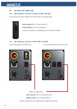
18.6 Operating the coolant unit without CNC controller
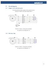
The switch shown below is located on the mains cable of the coolant pump.
Switch position ( 0 )
Pump switched off
Switch position ( I )
Pump switched on
(Caution: Coolant flow is controlled with the coolant shut-off valv
e)
18. Coolant unit (optional)
For machines with 1.4 kW drive motor For machines with 2.0 kW (hs) drive motor
Switch position ( 0 )
Pump switched off
Switch position ( I )
Pump switched on
(Caution: Coolant flow is controlled with the coolant shut-off valve)
18.7 Operating the coolant unit with CNC controller
Switch for coolant pump
Summary of Contents for F1410 LF
Page 41: ...41 7 Fitting and removing the tools 42 6 Spannen und Ausdrücken der Werkzeuge 1 2 3 4 5 ...
Page 98: ...98 16 Drawings and legends 16 12 Spindle Z axis with ball screws 16 12 1 F1410 LF F1410 LF hs ...
Page 126: ...126 16 Drawings and legends 16 22 Support arm for control panel 1 2 3 4 5 6 8 9 5 4 7 9 8 ...


