156
21. NC-rotary table (optional)
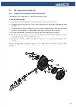
21.4 Removing the NC drive unit
The following adjustment work on the NC-rotary table can only be carried out with the NC drive unit
removed. The following section describes the removal of the NC drive unit.
In order to mount the drive unit of the NC-rotary table after successful adjustment, carry out the same
instructions in the reverse order.
1. Undo the screw (45) using a 5 mm Allen key and remove the washer (44).
2. Slightly undo the screw (29) using a 5 mm Allen key. This enables the motor holding plate (30) to
be swiveled.
3. Remove the three screws (28) using the Allen key. The motor holding plate may be swiveled to give
better access to the screws.
4. Tighten the screw (29) back up again.
5.
Open the cable duct (35) sufficiently to allow the cables to pass through easily.
6. Remove the motor hood (33) from the motor holding plate whilst also slackening the motor cable.
7. Slightly undo the four nuts (36) using an 8 mm wrench.
8. Loosen the belt tension by moving the motor (37) and remove the toothed belt (31) from the belt
pulley (32)
9. Loosen the screws (13) and remove with the washer (8).
10. Remove the belt pulley (32).
11. Undo the screw (29).
12. Remove the motor holding plate (30).
28
33
34
35
44
37 38
40 41 42
43
36
39
45
27
30
31
32
13
29
8
Summary of Contents for F1410 LF
Page 41: ...41 7 Fitting and removing the tools 42 6 Spannen und Ausdrücken der Werkzeuge 1 2 3 4 5 ...
Page 98: ...98 16 Drawings and legends 16 12 Spindle Z axis with ball screws 16 12 1 F1410 LF F1410 LF hs ...
Page 126: ...126 16 Drawings and legends 16 22 Support arm for control panel 1 2 3 4 5 6 8 9 5 4 7 9 8 ...

