3
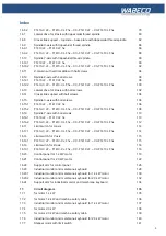
Index
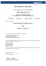
Declaration of conformity F1410 LF – F1410 LF hs
7
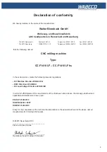
Declaration of conformity F1410-C LF – F1410-C LF hs
8
Declaration of conformity CC-F1410 LF – CC-F1410 LF hs
9
1.
Important safety notes
10
1.1
Intended use
10
1.2
Improper and incorrect use
10
1.3
Modifications to the machine
10
1.4
Safety regulations for proper use
10
1.5
Safety features
13
1.5.1
for all milling machines
13
1.5.2
for milling machines for the installation of a CNC controller and
13
for CNC milling machines
1.5.3
for CNC milling machines
13
1.6
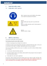
Explanations of the symbols
14
2.
Delivery and set up
14
2.1
Transporting the machine
15
2.2
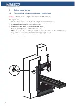
Transport-lock on milling machines with ball screws
16
3.
Putting into operation
17
3.1
for all milling machines
17
3.2
for all CNC machines
17
3.2.1
Setting up and connecting the control computer
17
4.
Specifications regarding the machine
18
4.1
Identification of the model
18
4.2
F1410 LF – F1410 LF hs
18
4.2.1
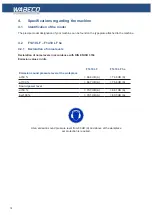
Declaration of noise levels
18
4.2.2
Technical data
19
4.2.3
Dimensions F1410 LF (1.4 kW) with trapezoidal thread spindle
20
4.2.4
Dimensions F1410 LF (1.4 kW) with ball screws
21
4.2.5
Dimensions F1410 LF hs (2.0 kW) with trapezoidal thread spindle
22
4.2.6
Dimensions F1410 LF hs (2.0 kW) with ball screws
23
4.3
F1410-C LF – F1410-C LF hs
24
4.3.1
Declaration of noise levels
24
4.3.2
Technical data
25
4.3.3
Dimensions F1410-C LF (1.4 kW) with trapezoidal thread spindle
26
4.3.4
Dimensions F1410-C LF (1.4 kW) with ball screws
27
4.3.5
Dimensions F1410-C LF hs (2.0 kW) with trapezoidal thread spindle
28
4.3.6
Dimensions F1410-C LF hs (2.0 kW) with ball screws
29
4.4
CC-F1410 LF – CC-F1410 LF hs
30
4.4.1
Declaration of noise levels
30
4.4.2
Technical data
31
4.4.3
Dimensions CC-F1410 LF (1.4 kW) with trapezoidal threaded spindle
32
4.4.4
Dimensions CC-F1410 LF (1.4 kW) with ball screws
33
4.4.5
Dimensions CC-F1410 LF hs (2.0 kW) with trapezoidal threaded spindle
34
Summary of Contents for F1410 LF
Page 41: ...41 7 Fitting and removing the tools 42 6 Spannen und Ausdrücken der Werkzeuge 1 2 3 4 5 ...
Page 98: ...98 16 Drawings and legends 16 12 Spindle Z axis with ball screws 16 12 1 F1410 LF F1410 LF hs ...
Page 126: ...126 16 Drawings and legends 16 22 Support arm for control panel 1 2 3 4 5 6 8 9 5 4 7 9 8 ...

