54
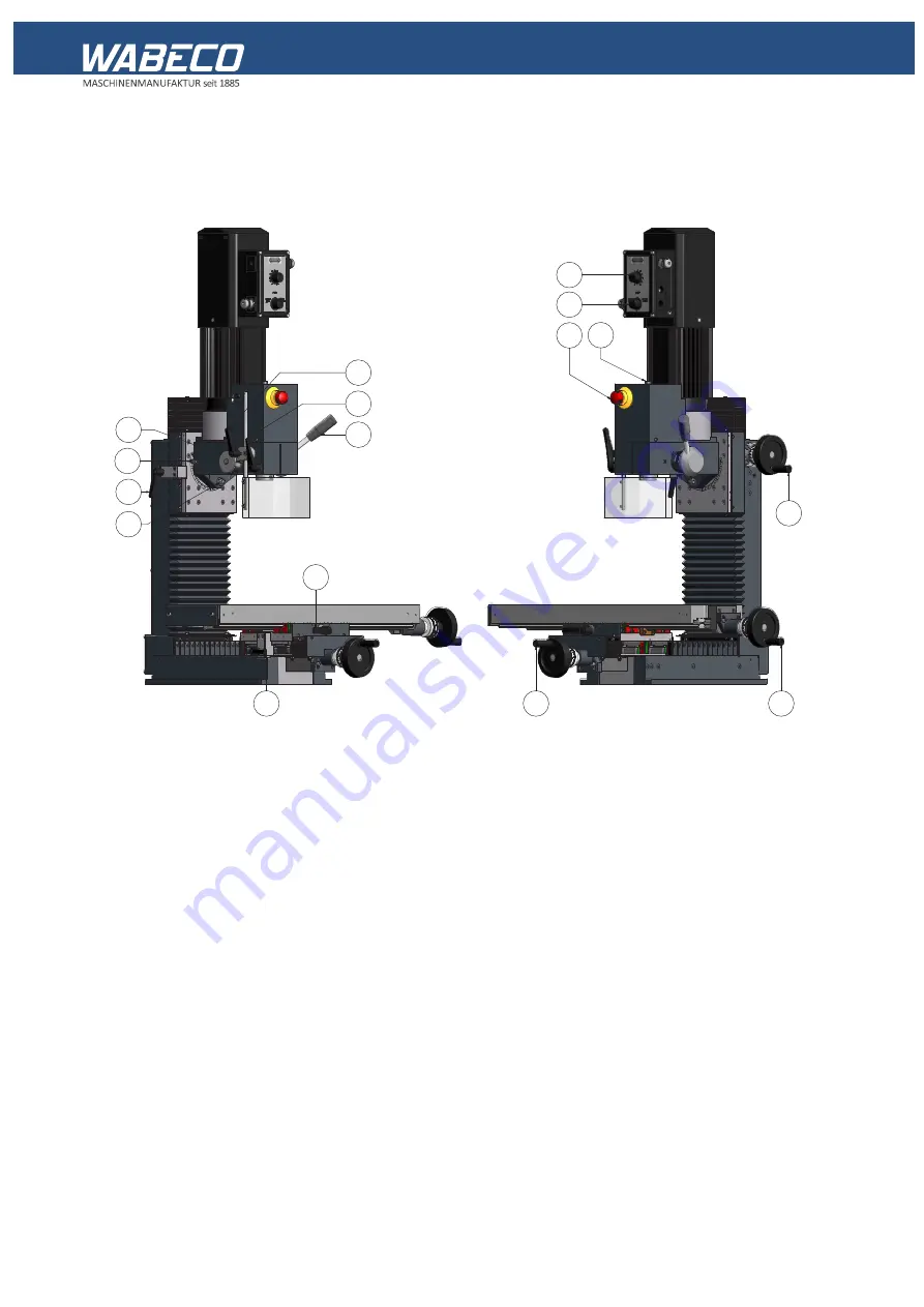
15. Control elements
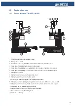
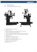
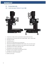
15.2 Control elements F1410 LF hs (2.0 kW)
1. Potentiometer rotating knob for speed selection of the electrical drive motor
2. 3-setting switch of the electrical drive motor (START RIGHT - STOP - START LEFT)
3. Emergency off switch
4. Tool tightening screw
5. Hand wheel for setting the boring and milling depth
6. Hand wheel for adjusting the longitudinal motion (X-axis) oft he cross slide support
7. Hand wheel for adjusting the transverse motion (Y-axis) of the cross slide support
8. Clamping lever for securing the protective hood
9. Clamping lever for securing the tool spindle
10. Activation lever for moving the tool spindle (sleeve stroke)
11. Clamping lever for adjusting the longitudinal motion (X-axis) of the cross slide support
12. Clamping lever for securing the transverse motion (Y-axis) at the cross slide support
13. Hexagonal nut for swiveling the milling head
14. Clamping lever for setting the boring and milling depth
15. 15. Index bolt for securing the milling head
16. Depth stop for boring
8
15
14
13
12
11
7
6
5
16
9
10
1
2
4
3
Summary of Contents for F1410 LF
Page 41: ...41 7 Fitting and removing the tools 42 6 Spannen und Ausdrücken der Werkzeuge 1 2 3 4 5 ...
Page 98: ...98 16 Drawings and legends 16 12 Spindle Z axis with ball screws 16 12 1 F1410 LF F1410 LF hs ...
Page 126: ...126 16 Drawings and legends 16 22 Support arm for control panel 1 2 3 4 5 6 8 9 5 4 7 9 8 ...


