63
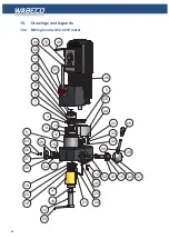
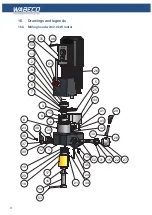
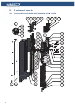
16. Drawings and legends
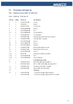
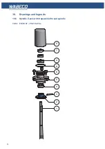
16.2 Electronic hood with 1.4 kW motor
16.2.1 F1410 LF – F1410-C LF
Part no. Items
Order no.
Description
1
1
51401212-00011
Cover
2
1
51501402
Board
3
1
51401211-0001
Cover hood
4
4
16196500004008
Screw
5
4
16193400004000
Nut
5.1
4
16167980004000
Fanned washer
6
1
51500606-0001
On-Off switch
7
1
51500807-0002
Potentiometer with cable and connector
7.1
1
51500807-00021
Potentiometer. complete
8
4
16179810003095
Screw
8.1
4
16191200004010
Screw
8.2
4
16112500004000
Washer
9
1
51500401-0002
Board holder without cut-out
9.1
1
51500401-0003
Board holder with cut-out
10
1
16191200004020
Screw
10.1
1
51501304
Symbol for earthed connection
10.2
2
16193400004000
Nut
10.3
2
16167980004000
Fanned washer
11
Tool tightening screw
11
1
91200010130-01
MT2 with tightening thread M10
1
91200012160-01
MT3 or ISO30 with tightening thread M12
12
1
51500624-0001
Emergency off switch, complete
13
1
51500920-0002
Mains cable with strain relief
15
Allen key
15
1
51007430-0001
8 mm for tool tightening screw MT2
1
51007440-0001
10 mm for tool tightening screw MT3 or ISO30
Summary of Contents for F1410 LF
Page 41: ...41 7 Fitting and removing the tools 42 6 Spannen und Ausdrücken der Werkzeuge 1 2 3 4 5 ...
Page 98: ...98 16 Drawings and legends 16 12 Spindle Z axis with ball screws 16 12 1 F1410 LF F1410 LF hs ...
Page 126: ...126 16 Drawings and legends 16 22 Support arm for control panel 1 2 3 4 5 6 8 9 5 4 7 9 8 ...


