POW-R-DRIVE II
9
Operator should always change sides for opposite
rotation.
I. SET UP PROCEDURE (all models):
1.
Insert valve key and socket into valve.
2.
Install stop collar at a comfortable operating
height to support the weight of the Pow-R-
Drive II.
3.
Mount the Pow-R-Drive II on the valve key
and rest on stop collar. Connect the power
source.
4.
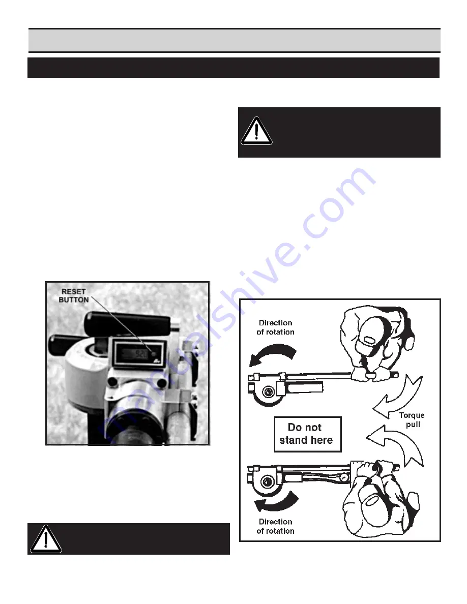
Zero the counter when valve is ready to be
turned by pressing the red reset button on the
counter face (Figure 1). Always use the
counter to determine the number of rotations
the valve has turned.
5.
Determine direction of valve rotation and which
side of Pow-R-Drive to operate. The operator
should stand on the side of the machine which
allows the torque to
PULL
the machine handle
away from his body.
FIGURE 1
SECTION IV
SET-UP AND OPERATION (cont.)
II. OPERATOR POSITIONING
Standing on the wrong side of the machine will allow
the handle to
PUSH
against the operator and can
knock him off balance or pin him against an obstacle
if torque suddenly increases. When positioned prop-
erly, an increase in torque will
PULL
the handle and
control out of the operator's hand and stop the ma-
chine (See illustrations below).
IMPORTANT:
Always refer to the manual or the
valve direction decal
located on valve handle for
correct operation positions.
CAUTION: The Pow-R-Drive II is capable of
producing up to 800 ft./lbs. of torque to turn
valves. It is very important that proper proce-
dure be exercised when using the valve operat-
ing machine.
CAUTION: Always operate the Pow-R-Drive II at
the lowest torque valve acceptable to turn the
valve.
Summary of Contents for POW-R-DRIVE II
Page 2: ......
Page 7: ...POW R DRIVE II 7 Set Up Operating Procedures Section IV ...
Page 17: ...POW R DRIVE II 17 SECTION V MISCELLANEOUS CHARTS AND GRAPHS ...
Page 20: ......
Page 21: ...POW R DRIVE II 21 SECTION VI MAINTENANCE ...
Page 23: ...POW R DRIVE II 23 SECTION VII PARTS LISTS EXPLODED VIEW DRAWINGS ...
Page 25: ...25 ...
Page 27: ...27 ...
Page 29: ...11 080 00 181 061 041 ...
Page 31: ...31 081 ...
Page 33: ...33 081 ...
Page 35: ...35 ...
Page 37: ...37 ...
Page 38: ...POW R DRIVE II Electrical Schematics Eibenstock Milwaukee Electric RevolutionCounter Wire 38 ...
Page 39: ...39 ...
Page 40: ...POW R DRIVE II 40 SECTION VIII VALVE EXCERCISING LOG ...


